In the same manner, connect the 7-1/2" brown wire from "K" on the
left to "K" on the right. Route the wire as shown in the Pictorial.
~
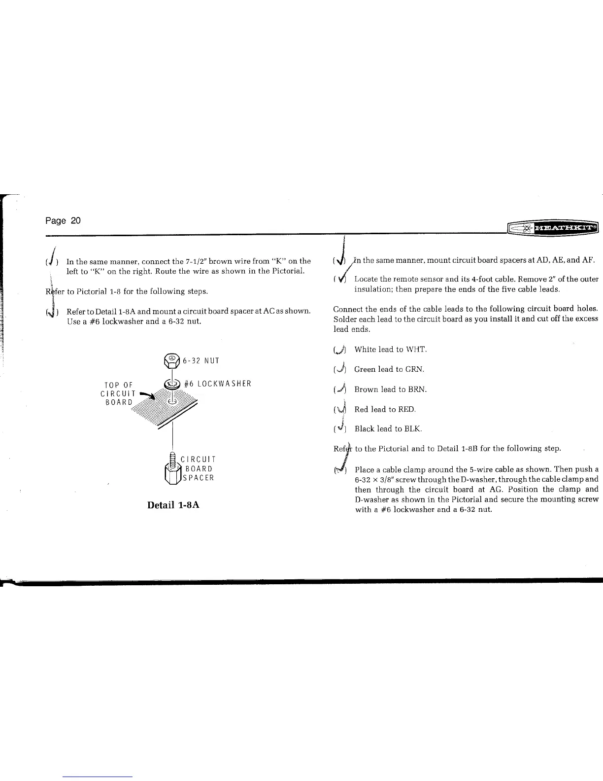
Ryfer to Pictorial 1-8 for the following steps.
(J)
Refer to Detaill-8A and mount a circuit board spacer at AC as shown.
Use a #6 lockwasher and a 6-32 nut.
®
6-32 NUT
TOP OF.~ #6 LOCKWASHER
c:~~~~:~
~ CIRCUIT
~ BOARD
lJj.JSPACER
I
(J
)n the same manner, mount circuit board spacers at AD,AE,and AF.
(.;; Locate the remote sensor and its 4-foot cable. Remove 2" ofthe outer
insulation; then prepare the ends of the five cable leads.
Connect the ends of the cable leads to the following circuit board holes.
Solder each lead to the circuit board as you install it and cut offthe excess
lead ends.
(••}) White lead to WHT.
('j~
Green lead to GRi"l.
,
(•.l)
Brown lead to BRN.
('4'~
Red lead to RED.
(J)
Black lead to BLK.
1
f~to the Pictorial and to Detail 1-8B for the following step.
r,)
Place a cable clamp around the 5-wire cable as shown. Then push a
6-32 x 3/8"screw through the D-washer, through the cable clamp and
then through the circuit board at AG. Position the clamp and
D-washer as shown in the Pictorial and secure the mounting screw
with a #6 lockwasher and a 6-32 nut.