p_a_ge_22 ~,
Refer to Pictorial 2-1 (Illustration Booklet, Page 6) for the following steps.
(J
Place a soft cloth on your work area. Then place the front panel on the
cloth as shown in the Pictorial.
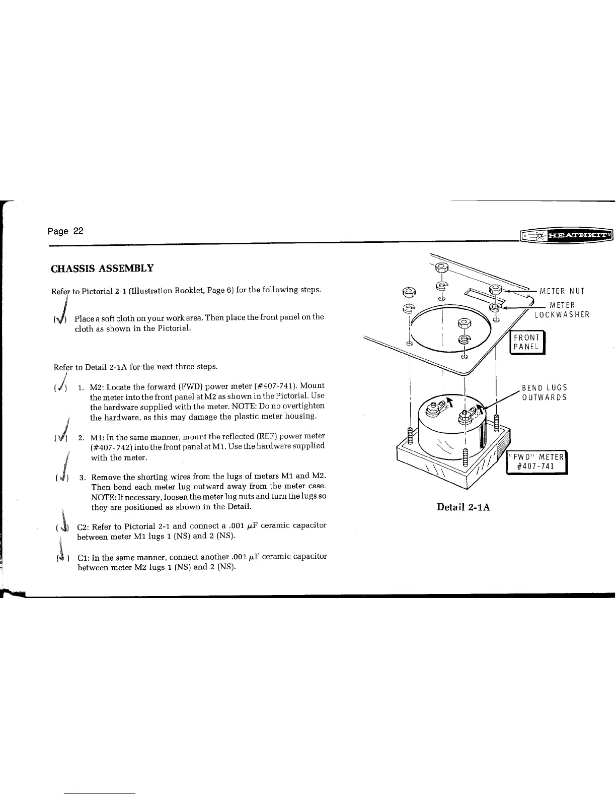
RefIJrto Detail 2-1A for the next three steps.
I
(A
1.
M2: Locate the forward (FWD) power meter (#407-741). Mount
the meter into the front panel at M2 as shown in the Pictorial. Use
the hardware supplied with the meter. NOTE: Do no overtighten
the hardware, as this may damage the plastic meter housing.
2. Ml: In the same manner, mount the reflected (REF)power meter
(#407- 742) into the front panel atMl. Use the hardware supplied
with the meter.
3. Remove the shorting wires from the lugs of meters Ml and M2.
Then bend each meter lug outward away from the meter case.
NOTE: Ifnecessary, loosen the meter lug nuts and turn the lugs so
they are positioned as shown in the Detail.
C2: Refer to Pictorial 2-1 and connect a .001
JLF
ceramic capacitor
between meter Ml lugs 1 (NS) and 2 (NS).
Cl: In the same manner, connect another .001
JLF
ceramic capacitor
between meter M2 lugs 1 (NS) and 2 (NS).