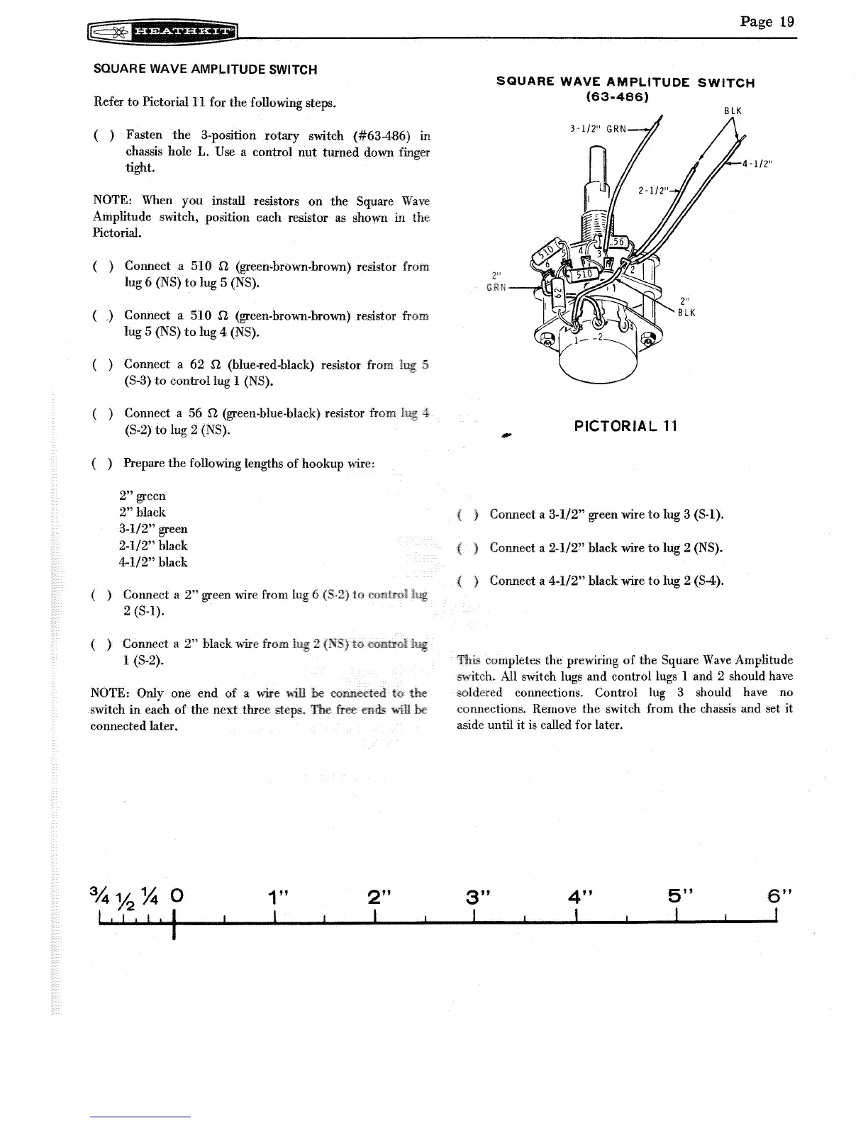
SQUARE WAVE AMPLITUDE SWITCH
Refer
to
Pictorial 11 for the following steps.
( ) Fasten
the
3-position
rotary
switch
(#63486)
in
chassis hole L. Use a control
nut
turned down finger
tight.
NOTE: When you install resistors on the Square
Wave
Amplitude switch, position each resistor
as
shown
in
the
Pictorial.
( ) Connect a
510
n.
(green-brown-brown) resistor from
lug 6
(NS)
to
lug 5 (NS).
(
->
Connect a 510
n.
(green-brown-brown) resistor
lug 5
(NS)
to
lug 4 (NS).
( ) Connect a 62 Q (blue-red-black) resistor from
(S-3)
to
control lug 1 (NS).
( ) Connect a 56
n.
(green-blue-black) resistor from
(S-2)
to
lug 2 (NS).
( ) Prepare
the
following lengths
of
hookup wire:
2"
green
2"
black
3-1/2" green
2-1/2" black
4-1/2" black
( ) Connect a
2"
green wire from 6
2 (S-l).
( ) Connect a
2"
black wire
1 (S-2).
NOTE: Only
one
end
of
a wire
switch
in
each
of
the
next
three
connected later.
1"
I
2
2"
I
Page
19
SQUARE
WAVE
AMPLITUDE
SWITCH
(63-486)
BLK
PICTORIAL
11
-
Connect a 3-1/2" green wire
to
lug 3 (S-l).
Connect a 2-1/2" black wire
to
lug 2 (NS).
Connect a 4-1/2" black wire
to
lug 2
(S4).
completes the prewiring
of
the
Square
Wave
Amplitude
switch. All switch lugs and control lugs 1 and 2 should have
soldered connections. Control lug 3 should have no
connections. Remove
the
switch from
the
chassis and set
it
aside until
it
is
called for later.
3"
I
4"
I
5"
I
6"
,