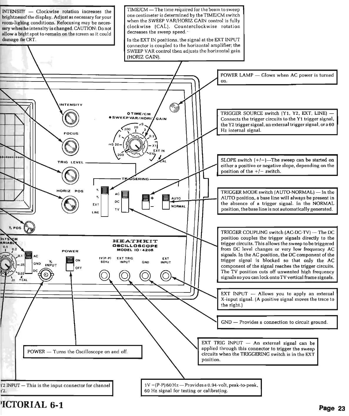
INTENSITY
- C
lo
ckwi
se
rotation increases the
brightne
ss
of
the
display
.
Adju
st as necessa
ry
for your
room-light
ing
conditions
. Refocusing may
be
neces-
sary when
the
inten
sity
is
changed. CAUTION: Do not
allow a b
right
spo
t
to
remain
on the screen as it could
damage
the
CRT
.
Y,
v,
EXT
LINE
IV
(
P·P)
60Hz
TIME/
CM
-
Th
e time required for the be
am
to
sw
eep
one centimeter is
det
e
rmined
by the TIME/CM switch
when
the
SWEEP
VAR
/HORIZ GAIN control is fully
clockwise
(CAL).
Counterclockwi
se
rotation
decreases
the
sweep speed.·
In
the
EXT
IN
po
sit
ion
s,
the
signal
at
the
EXT
INPUT
co
nne
ctor is
co
upled
to
the
horizontal
amp
lifier;
th
e
SWEEP
VA
R co
ntr
ol
th
en
adjusts the horizontal ga
in
(HORIZ GAIN).
:H:EA.T:H:KXT
DBCILLDBCDPE
MODEL
10 -
42015
E
XT
TRIG
INPUT
GNO
POWER LAMP - Glows
when
AC
power
is
turn
ed
on.
TRIGGER SOURCE switch
(Yl
, Y2,
EXT
, LINE) -
Connects
the
tr
igger circui
ts
to the
Yl
trigger
signa
l,
the
Y2 trigger signal,
an
external trigger signal,
or
a
60
Hz
in
te
rn
al signal.
SLOPE
switch
(+/-)-The
sweep
can
be
started
on
ei
ther
a positive or negative slope, d
epen
ding
on
the
posi
tion
of
the
+/-
switch.
T
RIGGER
MODE
switc
h
(AUTO-NORMAL)-
In
the
~~-~...;...;..;-.-1
AUTO
position
, a base
line
will always
be
present
in
the
absence of a trigger signal.
In
the
NORMAL
position,
the
base
lin
e
is
not
automa
tically generated.
EXT
INPUT
TRIGGER COUPLING
switch
(AC-DC-TV)-
The
DC
position
co
upl
es
the
trigger sig
nal
s directly
to
the
trigger circ
uit
s.
This
a
llows
th
e
sweep
to be triggered
from DC level
changes
or very
low
frequency AC
signals. In
the
AC
position
,
the
DC
component
of
the
trigger signal
is
blo
cked
so
tha
t only
the
AC
c
ompon
e
nt
of
the
signal reaches
the
trigger circuits.
The
TV
position
c
ut
s off
unwant
ed
high
frequency
signals
so
you can
lo
ck
onto TV vertical frame signals.
EXT INPUT -
Allows
you
to
app
ly
an
external
X-
inp
ut
signa
l.
(A
positive signal moves
the
trace
to
the
right.)
GND - Provides a c
onnection
to circuit
gro
und
.
POWER -
Turns
the Oscilloscope on
and
off.
EXT
TRIG INPUT -
An
ext
erna
l signal can
be
app
lied
through
this
co
nnector
to trigger
the
sweep
circuits
when
the
TRIGGERING
switch
is
in
the
EXT
position
.
I
NPUT
-
This
is
th
e
input
c
on
nector for channel
'ICTORIAL
6-1
1 V - (P-P)
60Hz
- Provides a 0.94-volt. peak-to-peak,
60 Hz signal for testing
or
calibr
at_ing
.
Page 23