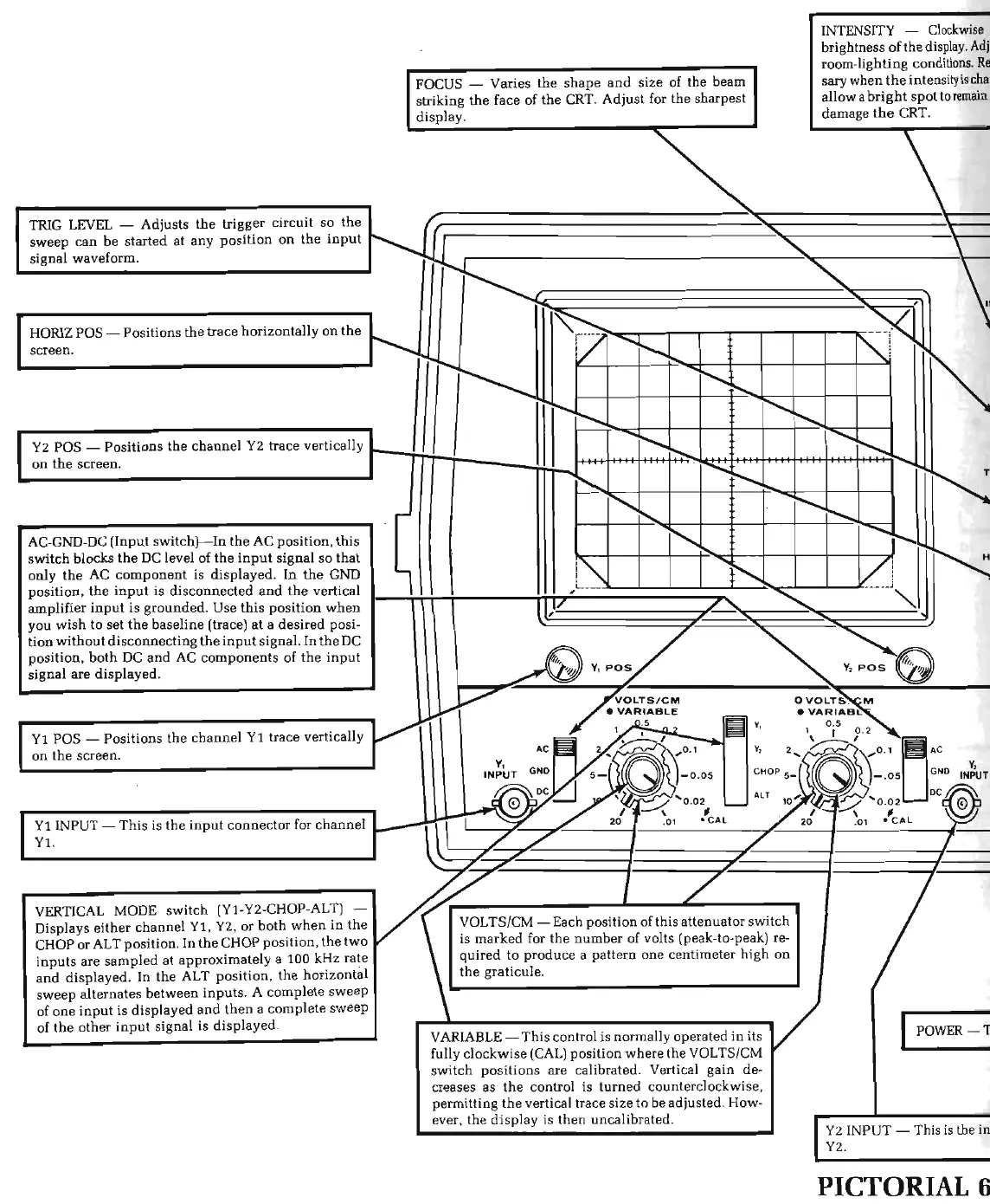
TRIG LEVEL - Adjusts
the
trigger circuit
so
the
sweep
can
be
started at
any
position
on
the
input
signal waveform.
HORIZ
POS-
Positions
the
trace horizontally
on
the
screen.
AC-GND-DC (Input switch)-
In
the
AC position,
this
swi
t
ch
blocks
the
DC
level of
the
input
signa
l
so
that
only
the
AC
component
is
displayed
. In
the
GND
position,
the
input
is disconnected
and
the
vertical
amplifier in
put
is
grounded. Use
this
position
when
you wish to
set
the
baseline (trace) at a
desired
posi-
tion
wit
hout
disconnec
t
ing
the
input
signal.
In
the
DC
position,
both
DC
and
AC
components
of
the
input
signal
are
displaye
d.
FOCUS - Varies
the
shape
and
size of the beam
striking
the
face of
the
CRT.
Adjust
for
the
sharpest
display.
,
~
~--------------------~1
~~~
Yl
POS - Positions
the
channe
l
Yl
trace vertically
V""
on
the
screen.
VERTICAL MODE
switch
(Yl-Y2-CHOP-ALT) -
v«
/ /
Displays either
channel
Yl
, Y2,
or
both
when
in
the
yoLTS/CM-
Each position of this attenuator switch
CHOP or ALT position. In
the
CHOP position,
the
two
ts
marked
for
the
number
of volts (peak-to-peak) re-
in
puts
are
sampled at approximately a 100 kHz rate
quired
to
produce a pattern
one
centimeter high
on
and
displayed. In
the
ALT
position
,
the
horizontal
the
graticule.
INTENSITY -
Clockwise
brightness of
the
display.
Ad
j
room-lighting conditions.
Re
sary when
the
intensity
is
cha
allow a
bright
spot
to
remain
damage
the
CRT.
1
I
sweep
alternates
between
inputs.
A complete
sweep
._
___________________
__.
of one
input
is displayed
and
then
a complete
sweep
~
of
the
other
input
signa
l is
disp
layed.
r-
.....
..._
__________________
,.
VARIABLE-
This
control is normally operated
in
its
fully clockwise
(CAL)
position
wher
e
the
VOL
TS/CM
switch
po
sitions
ar
e calibrated. Vertical
gain
de
-
creases as
the
control is
turn
ed counterclockwise,
permitting
th
e vertical trace size to be adjusted. How-
I
POWER-Tl
ever,
the
disp
lay is
then
uncalibrated.
r
Y2
I
NPUT-
This
is
the
in~
I
Y2.
PICTORIAL
6·