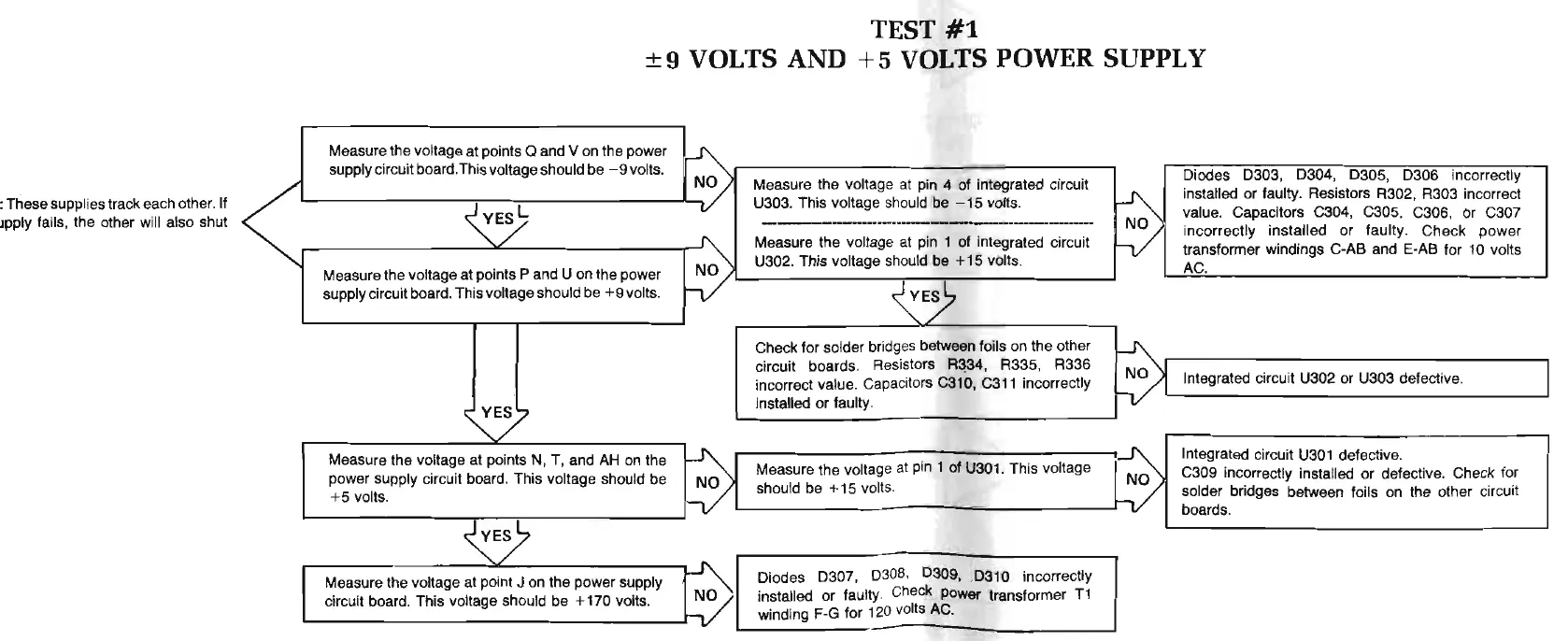
TEST
#1
+9
VOLTS
AND
+5
VOLTS POWER SUPPLY
'
:These supplies track each other.
If
Jpply fails, the other will also shut
Measure the voltage at points
Q and V on the power
S>
supply c
ir
cuit board.This voltage should be - 9 volts.
Diodes D303,
D304,
030
5, D306 incorrectly
Measure the voltage at pin 4 of integrated circuit
~~
U303. This voltage should be
-15
volts.
~
installed or faulty. Resistors R302, R303 incorrect
_______
..
-
v
al
ue. Capacitors C304, C305, C306, or C307
,3>
Measure the voltage at pin 1 of integrated circuit
~
incorrectly installed or faulty. Check power
U302. This voltage should be
+15
volts.
transformer windings C-AB and E·AB for
10
volts
Measure the voltage at points P and U on the power
AC.
supply circuit board. This voltage should be
+9
volts.
~~
Check for solder bridges between foils on the other
~
circuit
boards.
Resistors
R~4
,
R335, R336
incorrect value. Capacitors C310,
C311
incorrectly
Integrated circuit U302 or U303 defective.
~
installed or faulty.
Measure the voltage at points N, T, and
AH
on the
~
r3>
Integrated circuit
U301
defective.
Measure the voltage at pin 1 of
U301
. This voltage
power supply circuit board. This voltage should be
C309 incorrectly installed or defective. Check for
+5
volts.
h/
should be + 15 vol
ts
.
solder
br
idges between foils on the other
ci
rcuit
board
s.
~E?
8>
Measure the voltage at point J on the power supply
Diodes
0307,
D308
,
D309, .D310
incorrectly
circuit board. This voltage should be + 170 volts.
installed or faulty. Check power transformer
T1
winding F·G for 120 volts
AC.