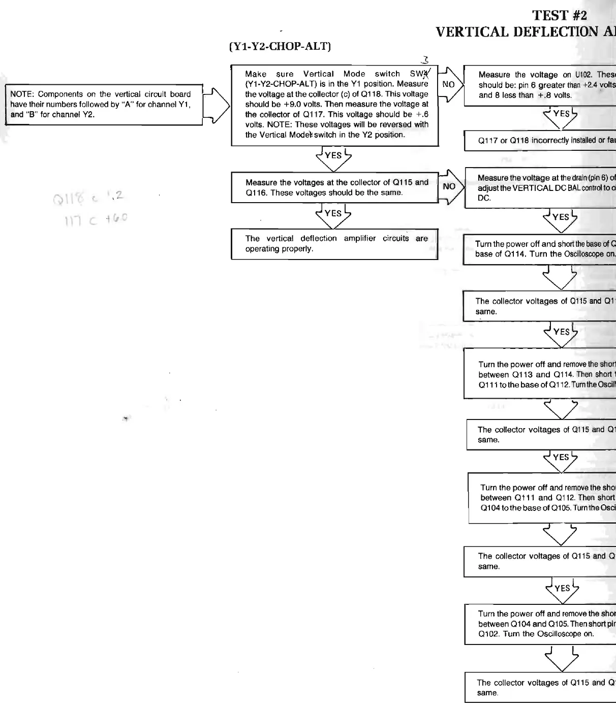
NOTE: Components
on
the vertical circuit board
have their numbers followed by "A" f
or
channel
Y1
,
and
"B" for channel Y2.
')\I
.
'--
,
z_
\)l
C
1&C
(Yl-
Y2-CHOP-ALT)
Make
sure
Vertical
Mode
switch
SW
'f.
(Y1-Y2-CHOP-ALT)
is
in the
Y1
position. Measure
the voltage at the collector (c) of
a118.
This voltage
should be
+9
.0 volts. Then measure the voltage at
the collector of
a111.
This voltage should
be
+.6
volts. NOTE: These voltages will
be
reversed with
the Vertical Mode
'h
witch in the Y2 position.
Measure the voltages at the collector of
a115
and
a116.
These voltages should be the same.
The
vertical deflection amplifier circuits are
operating properly.
TEST #2
VERTICAL
DEFLECTION
A1
Measure the
voltage
on
U102
.
Thes1
should be: pin 6 greater
than
+2.4 volts
and 8 less than + .8 volts. •
a111
or
a118
incorrectly
installed
or
fal
Measure the voltage
at
the
drain
(p
in 6) of
adjust the VERT
I
CAL
DC
BAL
control
too
l
DC.
Turn the power off
and
short
the
base
of a
base of
a114
.
Turn
the
Oscilloscope
on
.
The collector voltages of
0115
and
a1·
same.
Turn the
power
off and
remove
the short
between
a113
and
a114.
Then
short t
a111
to
the
base
ofa112
. TumtheOscill
The
collector voltages
of
0115
and
a 1
same.
Turn the
power
off
and
remove
the sho1
between
a111
and
a112.
Then
short
a104
to the
base
of
a105. TurntheOsci
The collector voltages of a115 and a ·
same.
Turn the
power
off
and
remove
the shor
between a 1
04
and
a1
05
. Then short pir
a102
. Turn the Oscillos
co
pe on.
The collector voltages of a115 and a ·
same.