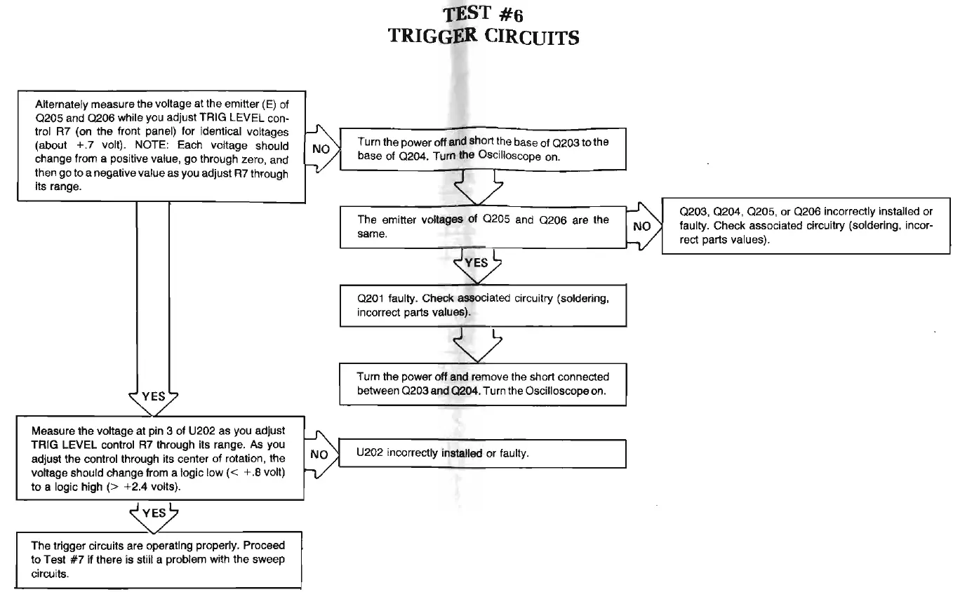
Alternately measure
the
voltage
at
the emitter (E)
of
0205
and
0206
while you adjust TRIG LEVEL con-
~
trol R7 (on the front panel) for identical voltages
(about
+.
7 volt). NOTE: Each voltage should
change from a positive value,
go
through zero, and
~
then
go
to a negative value as you adjust R7 through
its range.
~E;/
Measure
the
voltage at pin 3 of U202 as you adjust
~
TRIG
LEVEL control R7 through its range.
As
you
adjust
the
control through its center
of
rotation, the
voltage should change from a logic
low
( < + .8 volt)
to
a logic high (> +2.4 volts).
r------------~------------~
The
trigger circuits are operating properly. Proceed
to
Test
#7
if
there is still a problem with
the
sweep
circuits.
TEST
#6
TRIGGER CIRCUITS
Turn the power off
and
short the base of
0203
to
the
base
of
0204
. Turn the Oscilloscope on.
~)
The emitter voltages of
0205
and
0206
are
the
same.
~
0201
faulty. Check associated circuitry (soldering,
incorrect parts values).
v
Turn
the
power off and remove the short connected
between
0203
and
0204
. Turn the Oscilloscope on.
U202 incorrectly installed or faulty.
~
0203
,
0204
,
0205
, or
0206
incorrectly installed or
faulty. Check associated circuitry (soldering, incor-
h/
rect parts values).