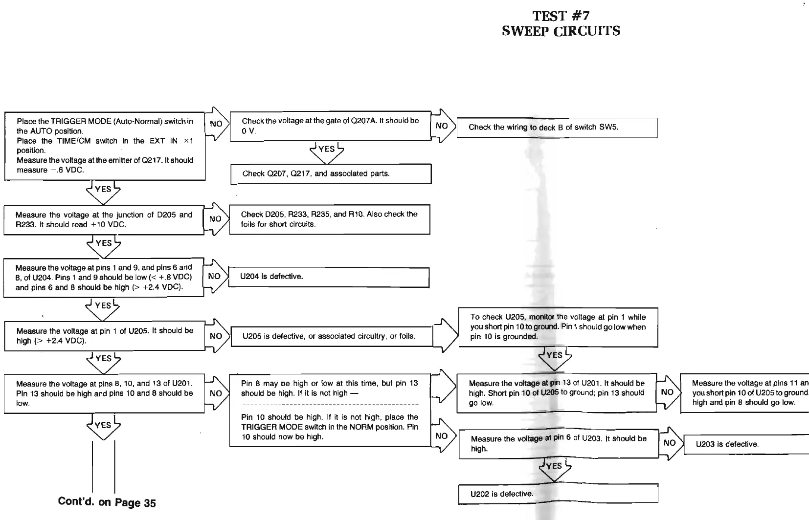
Place the TRIGGER MODE (Auto-Normal) switch in
the AUTO position.
Place the TIME/CM switch in the EXT IN x 1
position.
Measure the voltage at the emitter of
0217
. It should
measure - .6 VDC.
Measure the voltage at the junction
of
D205 and
R233. It should read + 10 VDC.
Measure the voltage at pins 1 and 9, and pins 6 and
8,
of
U204. Pins 1 and 9 should be
low(
< + .8 VDC)
and pins 6 and 8 should be high
(> +2.4 VDC).
Measure the voltage
at
pin 1 of U205.
It
should be
high
(> +2.4 VDC).
Measure the voltage at pins 8, 10, and
13
of
U201
.
Pin 13 should be high and pins 10 and 8 should be
low.
Cont'd. on Page 35
Check the voltage
at
the gate of
0207
A. It should be
0
v.
Check
0207
,
0217,
and associated parts.
Check D205, R233, R235, and R10. Also check the
foils for short circuits.
U204 is defective.
U205 is defecti
ve
, or associated circuitry,
or
foils.
Pin 8 may be high
or
low at this time, but pin 13
should be high. If it is not high -
Pin 10 should be high. If it is not high, place the
TRIGGER MODE switch in the NORM position. Pin
10
should now
be
high.
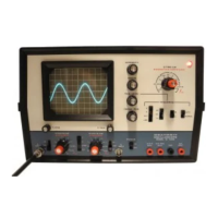
TEST
#7
SWEEP CIRCUITS
Check the wiring
to
deck B of switch SW5.
To
check U205, monitor the voltage at pin 1 while
you short pin 10
to
ground. Pin 1 should
go
low when
pin 10 is grounded.
Measure the voltage at pin 13 of U
201
. It should
be
high. Short pin 10
of
U205 to ground; pin 13 should
go
l
ow
.
Measure the voltage at pin 6 of U203. It should be
high.
U202 is defective.
Measure t
he
voltage at pi
ns
11 a
ll
you
s
ho
rt pin 10 of U205 to ground.
high and pin 8 should go low.
U203 is defectiv
e.