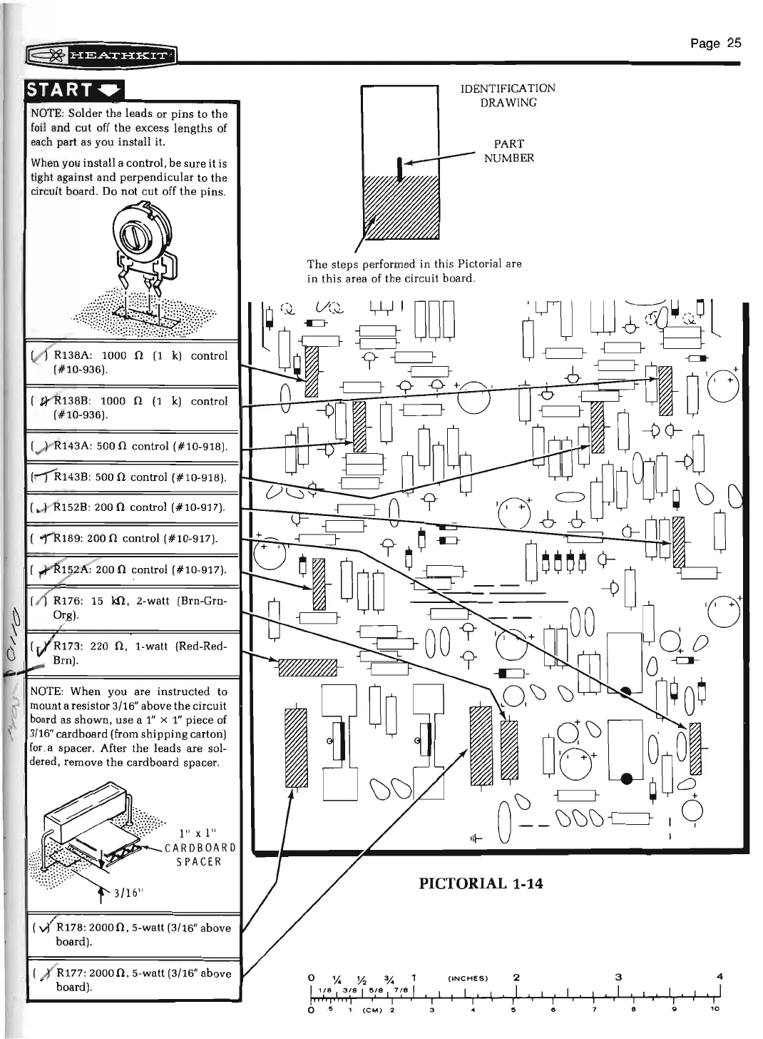
NOTE
: Solder
the
leads or
pins
to
the
foil
and
cut
off
the
excess
lengths
of
each part as you install it.
When you install a control, be
sure
it
is
tight against
and
perpendicular
to
the
circuit board. Do
not
cut
off
the
pins
.
(
~
138B
:
1000 0
(1
k)
control
(#10-936).
(
.,....l
143A: 500 0 control (#10-918).
(!"'")R.143B: 500 0 control (#10-918).
152B: 200
0 control (#10-917).
200
0 control (#10-917).
15
kn
, 2-watt (Brn-Grn-
220 0 , 1-watt (Red-Red-
you are
instructed
to
mount a resistor 3/16" above
the
circuit
board as
shown
,
use
a
1"
x
1"
piece of
3/
16"
card
board (from
shipping
carton)
for
. a
spacer
. After
the
leads
are sol-
dered, remove
the
cardboard
spacer
.
1"
X 1"
~
or--
CARDBOARD
SPACER
R178:
20000
, 5-watt (3/16" above
board).
R177:
20000
, 5-watt (3/16" above
board).
IDENTIFICATION
DRAWING
PART
NUMBER
The
steps performed in this Pictorial are
in
thi
s area of
the
circuit
bo
a
rd
.
•II-
PICTORIAL 1-14
0
y.
%
"4
(INCHES)
2
I
1(8
I
3~8
I
!S(B
I
1;8
1
I I
I
I I I I
I
I I
fl
j I I I
')
I
I
I
I
I I
0
.5
1
(CM)
2 3 5
"
Page
25
3
4
I
I
I I
I
I I
I
I
I
I
I
I
I
I
I
8
"
10