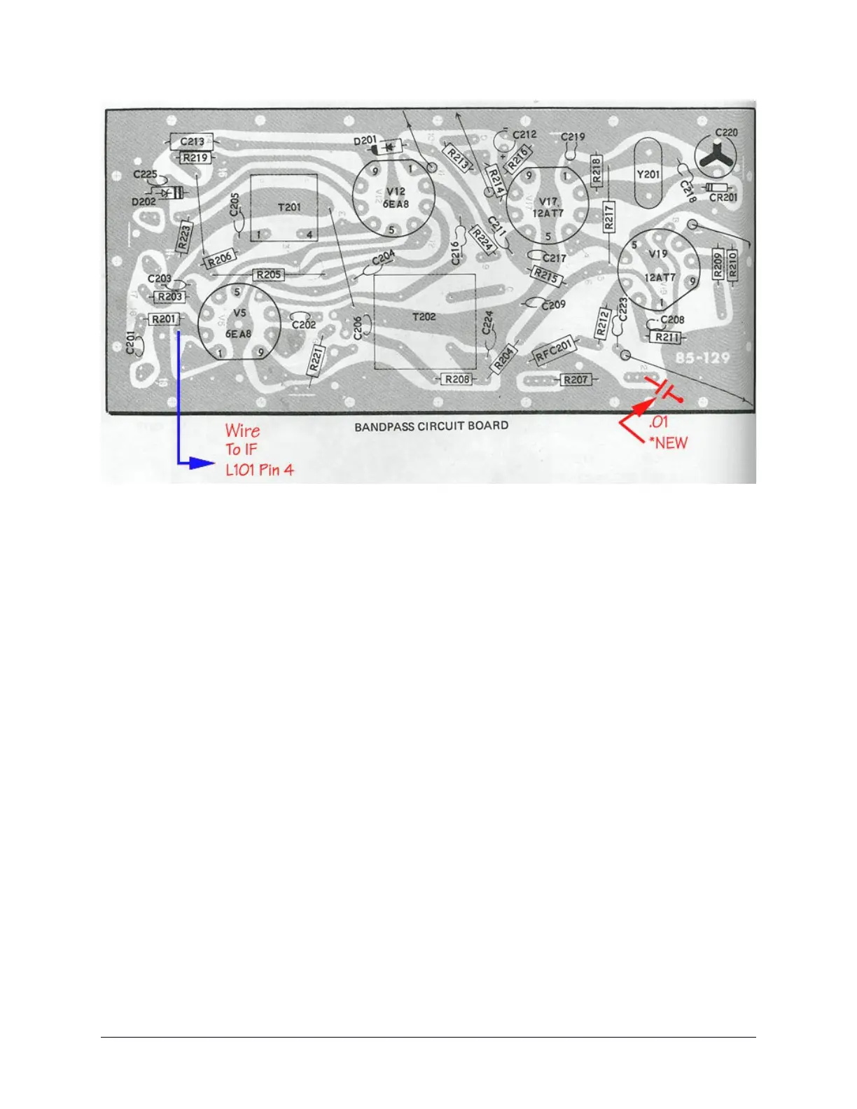
Figure 16. Bandpass Board Modifications
ac.6. I.F. Filter Passband Improvements
I believe the crystals that Heath supplied for the carrier oscillator were of fairly wide
tolerance, thus the frequencies of the LSB/USB/CW carrier injection may not be
properly positioned on the slope of the I.F. filter. This can affect both the receive and
transmit audio response to a great degree. Telltale signs of this are not having the same
audio response on USB and LSB, and reduced CW power output when using the CW
filter.
It is relatively easy to tell if the USB/LSB carrier insertion points aren’t placed
equidistant from the center of the I.F. filter passband. After the rig reaches a stable
operating temperature (1/2 hour) disconnect any antenna and peak the preselector for
maximum receiver gain. Next turn up the volume control to a slightly higher than normal
level and listen closely to the hiss coming from the speaker. Then switch to the opposite
sideband. The pitch of the receiver background noise should be the same if the USB &
LSB carriers are both placed equidistant from the filter center frequency.
If the carrier oscillator frequency is placed too far from the filter passband, the receive
and transmit signals will lack “lows” but the opposite sideband rejection will be high. If
the carrier oscillator frequency is placed too close to the filter center frequency, the
receive and transmit signals will have excessive “lows” and the opposite sideband
rejection and carrier suppression will suffer. Balance is the key.
Modifications Page 92