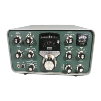
SEE BULLETIN NO: SB-102-5 DATED OCTOBER 29, 1973
ah.1.5. HW-101-4: Low Output on 40 Meters
OCTOBER 29, 1973
HW-101 BULLETIN NO: SSB TRANSCEIVER HW-101-4
1. REMOVE the 1-1/2" bare wire from hole 1 on the DRIVER PLATE circuit board & the
ground foil of the RF DRIVER board.
2. Connect a 3/4" bare wire between the ground foils of these same two boards.
3. REMOVE the 1-3/4" bare wire from hole 1 in the DRIVE GRID circuit board & the
ground foil of the RF DRIVER board.
4. Connect a 3/4" bare wire between the ground foils of these same two boards.
5. REMOVE the 2-3/4" bare wire which ties the ground foils of the circuit boards to the
shields.
6. REMOVE the coil cover. Then REMOVE four of the light spring clips & their
hardware as shown:
[[[NOTE: The pictorial shows removal of the set of clips & hardware located directly
down from the 2 holes in the cover; the other set to be removed is directly across and
down from the 3 holes in the cover.]]]
7. Readjust the driver grid & drive plate coils as instructed in the HW-101manual.
ah.1.6. HW-101-5: Alternate Method of Neutralizing the Final Amplifiers
MAY 23, 1974
HW-101 BULLETIN NO: SSB TRANSCEIVER HW-101-5
SEE BULLETIN NO: HW-100-3 DATED MAY 23, 1974.
ah.1.7. HW-101-5: Alternate Method of Neutralizing the Final Amplifiers
MAY 23, 1974
HW-101 BULLETIN NO: SSB TRANSCEIVER HW-101-5
NOTE: Be sure unit is off and power supply high voltage capacitors are discharged.
1. Disconnect final plates and screen grid. **
2. Turn unit on.
3. Rotate the band switch to 28.5.
4. Place the VTVM RF probe in the antenna connector.*
HW-101 Service Bulletins Page 137

 Loading...