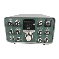
On my HW-101 I put the capacitors (silver mica’s) directly on the circuit board foils. I got
one sideband to sound the way I liked, and then simply adjusted the other sideband to
match it in audio response. I wound up using a 10pf cap in parallel with the LSB crystal,
100pf in series with the USB crystal, and 80pf in series with the CW carrier crystal.
Following these changes, the new carrier oscillator frequencies for my rig are 3393.51
kHz LSB, 3396.31 kHz USB, and 3395.38 for CW. The audio is perfectly balanced when
switching between sidebands, indicating a true I.F. filter center frequency of Heathkit
Crystal Filters of 3394.91 kHz. The CW power output while using the CW filter went
from 50 watts to 110 watts.
I also soldered a short loop of wire to the center lug of the carrier null pot to serve as a
test point to measure the carrier oscillator frequency. Be sure that once you have
determined the filter center-frequency, you place the oscillator frequencies no closer
than about 1.4 kHz and no further than 1.6 kHz from the filter center-frequency.
To recap, we are actually matching the response between USB & LSB by ear, then
verifying with a frequency counter that the carriers are no closer to the filter passband
than 1.4 kHz, and no further than 1.6 kHz. Even though we can match the pitch
between USB and LSB with our ear, we can't tell exactly WHERE they are -- only that
they are at the same point on the filter slope.
When the carrier oscillator frequencies are changed, the signal level of the oscillator
outputs may consequently change and therefore should be adjusted to be equal.
Connect a scope or RF probe to the carrier null pot center lug test point and switch
between sideband modes, checking for equality in level. If need be, adjust the value of
R6 or R7 to achieve equality. The level should be at least 1 volt RMS, or 3 volts P-P.
ac.7. Stabilizing Meter Zero Settings
S-meter zero setting instability is mainly caused by heat-related resistance changes in
the R106 22KΩ 1-watt resistor on the I.F. board. Replace R106 with a 22KΩ 2-watt
wirewound resistor.
Also, change R107 from 100KΩ ½ watt to 100KΩ 1 or 2 watt.
Note: R106 was changed to 33kΩ on revision level 5 of the IF board to improve the life
of V3. Changing to this value may also require changing the 330Ω resistor to 510Ω to
allow zeroing of the “S” Meter. This resistor does not have to be wirewound as stated, it
just should not be a carbon composition resistor for stability reasons.
The problem of the meter reading below zero during transmit while in the ALC position
is corrected by connecting a 10MΩ resistor from the meter Zero-Adjust pot pin 3, to pin
2 of T-102 on the I.F. board (hints from N4NRW).
Modifications Page 94

 Loading...