"GROUND
LOOPS” IN
AUDIO CABLES
Undermost
conditions, lower overall
hum
will
result if the shield on the input
cable is grounded
to the shell only
at
the
preamplifier
end,
leaving the
shield completely free
at
the
power ampli-
fier
connection.
If
hum is
objectionable
under operating
conditions,
experiment
by
reversing
this
cable.
Occasionally,
hum
will
develop
because of ground loops
between
a
phono
pickup
and
the preamplifier or
between
other program
sources and the
preamplifier.
Try
disconnecting
each input to the
preamplifier
in turn
until
the hum
level drops. Then experiment
by
opening
the
ground
return
at each end of the
cable
for
that particular
source.
As a
last
resort, try
an in-
dependent ground
conductor from
each program
source to
a
ground point,
with a short heavy
conductor from this point to
virtual
earth ground,
such as a
cold
water
pipe. Independent grounds
from the preamplifier
chassis
and
the
power amplifier chassis may also help.
This
procedure
should rarely
be
necessary and
is
mentioned
only
as
a desperate
measure.
If
required, an earn-
est investigation
of
the program
sources
is
in
order;
leakage
from their
power circuits to
ground
is indicated. Self-powered preamps must
be
grounded
to the
W-5M
chassis
with
a
grounding
wire
or through the audio
cable
shielding.
PHYSICAL
LOCATION OF
THE
AMPLIFIER
The
amplifier should
be
located
where it
is
protected from dampness,
where
it
is readily
ac-
cessible
and
where
adequate
ventilation is assured.
As
previously
mentioned,
the mounting feet
space
the
amplifier
above
the
mounting
surface to assure free
flow
of
air under and
up
through
the bottom chassis
cover.
An
inch
or
so of free
space
is
required
above
the amplifier
cover
.
The cover is
symmetrical and
may be
reversed
to
place
the controls and connectors on the rear
apron
if desired.
USE OF AC
OUTLETS
Two
AC
outlets are provided
on
the chassis
apron.
The
one
marked
AC NORMAL
is
not
con-
trolled
by
the switching circuit nor is it protected
by
the amplifier
fuse.
The
outlet
marked
AC
SWITCHED
is
controlled and fused.
Please
note
that total
load connected
to the
switched
outlet
should not exceed 150 watts;
otherwise the fuse will blow.
We
suggest
that the
AC NORMAL
outlet
be used
for
record
changers equipped with automatic
shut-off
switches
or other accessories for which independent switching
is desired. The
AC
SWITCHED
outlet will
be
convenient
for
tuners, tape recorders,
etc.
CAUTION:
Do
not
use
the switched
outlet for powering
professional
type turntables.
These units
are
equipped
with
interlocking mechanisms to lift idler pulleys
from
capstans and table
rims when they are turned
off.
If
the
turntable
switch is not used, the
idlers will
not
be
lifted and may
become
deformed.
GENERAL
NOTES
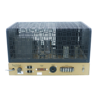
The
Heathkit
W-5M
Amplifier
incorporates several
features
which
might
bear
further
discussion,
although they have
all
been
mentioned previously
in
this
manual. Among
these
is
the unique
method used
for indicating exact balance
or cathode current between
the
KT66
output tubes. In
the
original
treatise
on the Williamson
amplifier,
Mr. D. T. N.
Williamson stated that
such
bal-
ance
was a "matter
of
some importance.
”
The
graph on Page 32
tends to support this
statement.
Observe
that the
reduction in harmonic
distortion
is
much
more
pronounced
at
lower
frequencies
becoming quite
critical in the 20
cps
region.
The
usual method
for
indicating
balance involves
connecting
a
milliammeter in series with each
cathode return, noting the
current
reading
and
adjusting
the
balance
control until
equal
cathode currents are
obtained
for
each
tube.
The
method
is
time-consuming, frequently inaccurate
and
requires
the
use
of
a
meter
not
readily
available.
The
"Bass-Bal"
method used in the
W- 5M
permits
indicating
exact
balance
without upsetting
circuit
conditions,
is
limited
in
accuracy
only
by the
sensitivity of the meter
and
requires
only
a simple
voltage indicator. Accuracy of meter
calibration
is
unimportant,
since it is
used
only for
indic-
ating
zero
potential
difference.
Even
if the meter
zero adjustment
is
defective,
the
balance set-
ting
will
be
indicated
perfectly provided the meter
shows
no
change
in deflection
when
connected
or
disconnected at
the
jacks.
The meter may be
left connected
without fear of
damage.
It
should
be
pointed out that adjustment
is
quite
stable
once
affected
and need
be
checked only
at infrequent
intervals.
Page
28

 Loading...