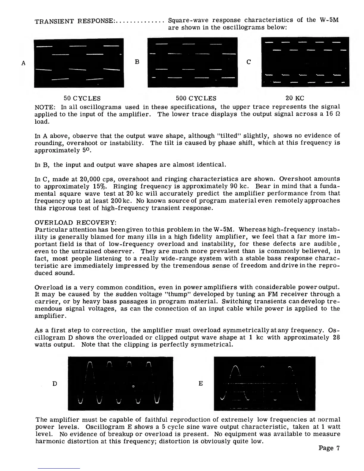
TRANSIENT
RESPONSE:
Square-wave
response
characteristics
of the
W-5M
are
shown in the
oscillograms
below:
50
CYCLES
500
CYCLES
20
KC
NOTE:
In
all oscillograms
used
in
these
specifications,
the upper trace
represents the
signal
applied
to the
input
of the amplifier. The
lower
trace
displays
the output
signal across
a 16 O
load.
In A
above, observe that
the
output
wave
shape,
although "tilted"
slightly,
shows
no evidence
of
rounding,
overshoot
or instability.
The
tilt
is caused by
phase
shift,
which
at
this
frequency is
approximately
5°.
In
B,
the input
and
output wave
shapes are
almost identical.
In
C,
made at
20,000
cps,
overshoot
and
ringing
characteristics are
shown.
Overshoot
amounts
to approximately
15%.
Ringing
frequency
is
approximately 90 kc. Bear
in
mind
that a
funda-
mental square
wave
test
at 20 kc
will
accurately predict the
amplifier
performance
from that
frequency up
to
at
least
200 kc.
No
known source
of program
material
even
remotely approaches
this rigorous test
of
high-frequency transient
response.
OVERLOAD
RECOVERY:
Particular attention has
been given
to
this
problem
in
theW-5M.
Whereas
high-frequency instab-
ility
is
generally blamed
for many ills in
a
high fidelity
amplifier, we feel
that a
far more
im-
portant field is that
of low-frequency
overload
and
instability, for these
defects are audible
,
even
to the
untrained
observer. They are
much
more prevalent
than
is
commonly
believed,
in
fact,
most people
listening
to a
really wide-range system
with
a
stable
bass
response
charac-
teristic are
immediately
impressed
by
the
tremendous sense
of freedom
and drive
in the repro-
duced
sound.
Overload is a
very common condition,
even in
power
amplifiers
with considerable power output.
It may be
caused by the sudden voltage "thump"
developed
by
tuning
an
FM
receiver through
a
carrier,
or
by
heavy
bass passages
in
program
material.
Switching transients
can
develop tre-
mendous
signal voltages,
as
can
the
connection of an
input
cable
while
power is applied to
the
amplifier.
As
a first
step
to correction,
the
amplifier must
overload
symmetrically
at
any
frequency.
Os-
cillogram
D
shows
the
overloaded or clipped output wave shape at
1
kc
with approximately
28
watts output.
Note that the
clipping
is
perfectly symmetrical.
c
c
c
c
A
'
o
E
—
—
:
y u u w
W
V V
.
. v
The
amplifier
must be
capable of
faithful reproduction
of extremely
low frequencies
at
normal
power
levels.
Oscillogram
E
shows a 5
cycle sine
wave
output characteristic, taken
at
1 watt
level.
No
evidence of
breakup
or
overload is
present.
No
equipment
was
available to measure
harmonic
distortion
at
this
frequency; distortion is obviously
quite low.
Page
7