12 Heatilator • CNXT Series • 4000-011 Rev N • 11/05
Fire Risk
Explosion Risk
Do NOT pack insulation or other combustibles between fi restops.
• ALWAYS maintain specifi ed clearances around venting and fi restop systems.
• Install fi restops as specifi ed.
Failure to keep insulation or other material away from vent pipe may cause fi re.
WARNING
The fi rst 90° elbow MUST be a starter elbow.
To replace the fi rst starter elbow with two 45° elbows, refer to Figure 5.4. All other 90° elbows can be replaced with two 45°
elbows.
General Rules:
• SUBTRACT 3 ft (914 mm) from the total H measurement for each 90° elbow installed horizontally.
SUBTRACT 1-1/2 ft (457 mm) from the total H measurement for each 45° elbow installed horizontally.
• A maximum of three 90° elbows (or six 45° elbows) may be used in any vent confi guration. Some elbows may be installed
horizontally. See Figure 5.6.
• Elbows may be placed back to back anywhere in the system as long as the fi rst 90° elbow is a starter elbow except as
shown in Figure 5.4.
• When penetrating a combustible wall, a wall shield fi restop must be installed.
• When penetrating a combustible ceiling, a ceiling fi restop must be installed.
H
1
V
1
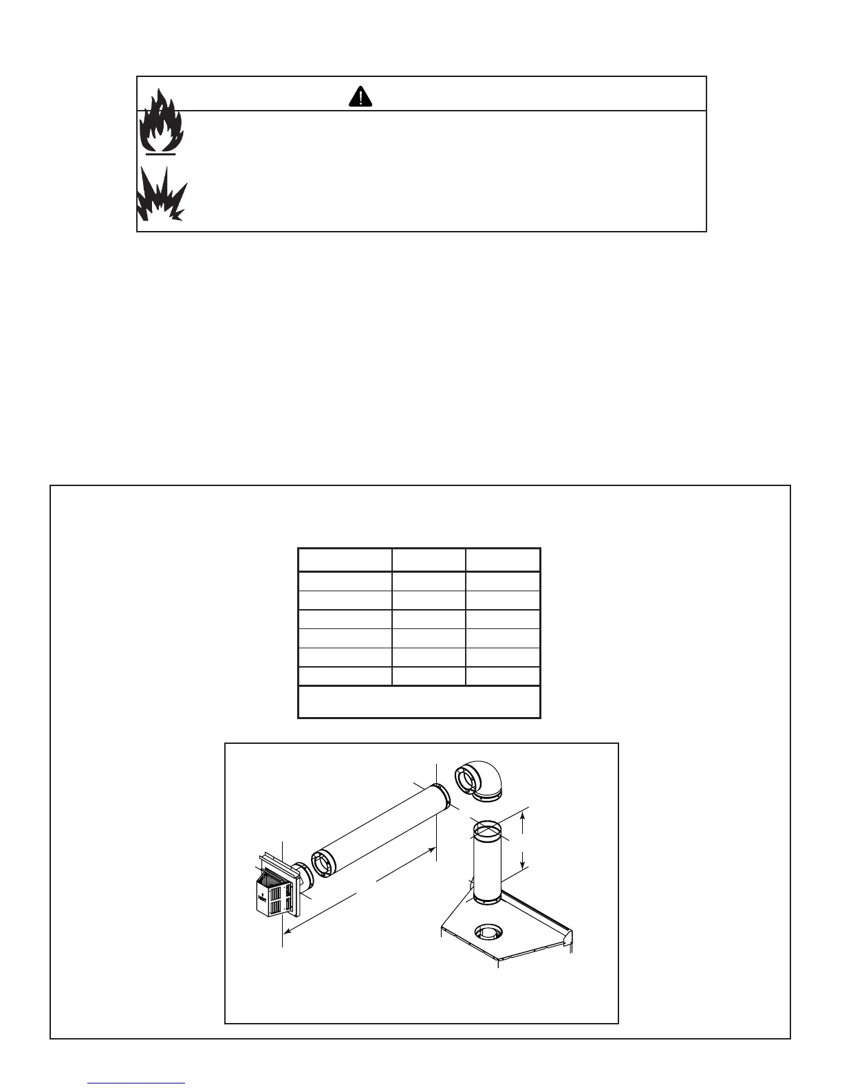
Figure 5.3 Top Vent-Horiztonal Termination-One Elbow
Table 5.1
V
1
min. V
1
max. H
1
max.
0* - 24 in./610mm
6 in./152 mm - 6 ft/1.83 m
12 in./305 mm - 11 ft/3.35 m
18 in./457 mm - 18 ft/5.49 m
24 in./610 mm - 25 ft/7.62 m
- 25 ft/7.62 m 25 ft/7.62 m
* You may install the elbow directly on top of the
appliance
D. Vent Diagrams
Top Vent—Horizontal Termination—One Elbow