6 Heatilator • CNXT Series • 4000-011 Rev N • 11/05
In addition to these framing dimensions, also reference the
following sections:
• Clearances and Mantel Projections (Sections 3.C. and 3.D.)
• Vent Clearances and Framing (Section 6)
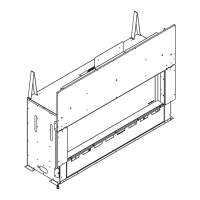
Rear vent
One 45° elbow
Horiz Term
Rear Vent
Two 90° elbows
Horiz Term
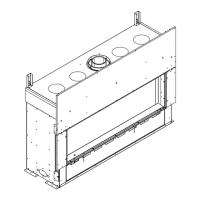
Rear Vent
One 90° elbow
Vert Term
Top Vent
One 90° elbow
Horiz Term
No elbows
Horiz Term
A
A
A
G
A
A
C
D
B
B
F
1 in. (25 mm) min.
pipe to combustibles
I
E
1/2 in. (13 mm) min.
appliance to
combustibles
E
I
1 in. (25 mm) min.
pipe to
combustibles
F
1/2 in. (13 mm) min.
appliance to
combustibles
Alcove
Installation
C
H
Drywall
A
Note:
• Illustrations refl ect typical installations and are FOR
DESIGN PURPOSES ONLY.
• Illustrations/diagrams are not drawn to scale.
• Actual installation may vary due to individual design
preference.
Fire Risk
Provide adequate clearance:
• Around air openings.
• For service access.
Locate appliance away from traffi c areas.
WARNING
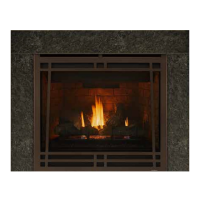
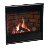
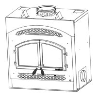
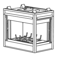
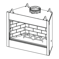
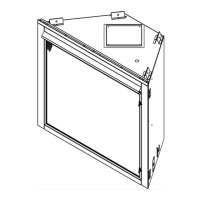
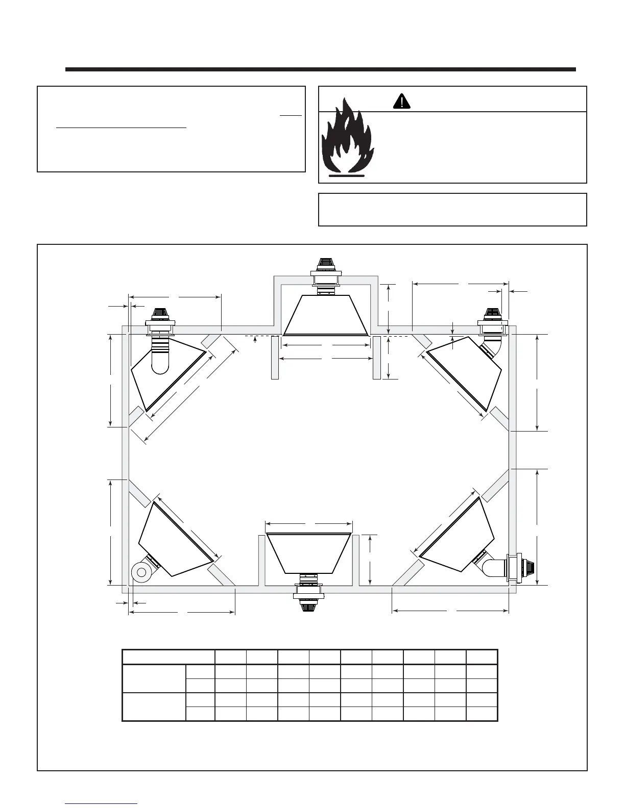
A. Select Appliance Location
When selecting a location for your appliance it is important to
consider the required clearances to walls (See Figure 3.1).
Note: For actual appliance dimensions refer to
Section 16.
Figure 3.1 Appliance Locations
3
Framing and Clearances
Model # A B C D E F G H I
CNXT70I Series in. 42 50-5/8 23-1/2 71-5/8 50-5/8 52-5/8 43 48 59-3/4
mm 1067 1286 597 1819 1286 1337 1092 1220 1518
CNXT90I Series in. 48 55-1/4 23-1/2 78-1/4 55-1/4 55-1/4 49 48 59-3/4
mm 1219 1403 597 1988 1403 1403 1245 1220 1518