Heatilator • CNXT Series • 4000-011 Rev N • 11/05 25
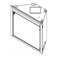
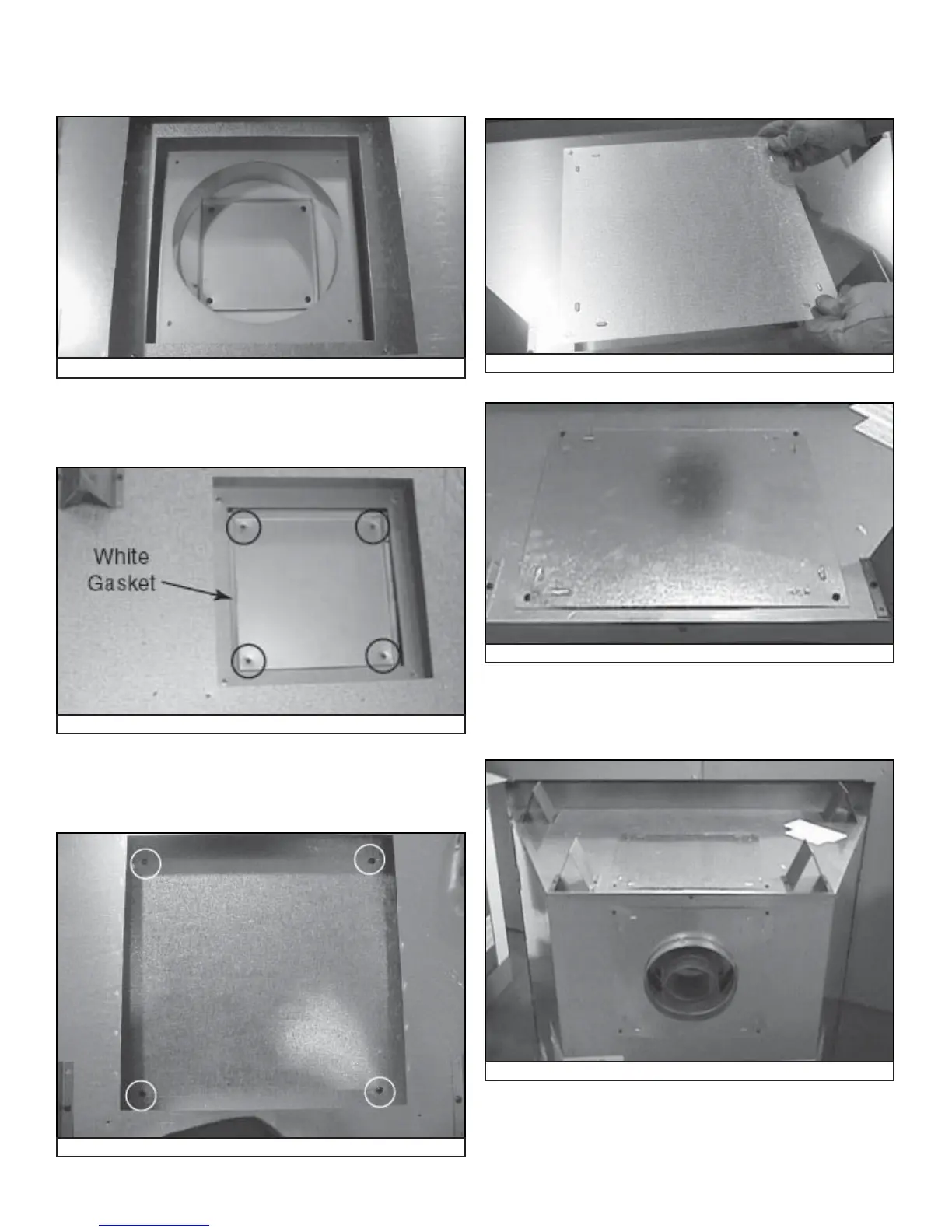
Figure 7.12 Place Inner Cover Plate on Top of Appliance.
• Place the inner cover plate and white gasket (removed
in Figure 7.8) on the appliance top. Place four screws to
hold the inner cover plate in place. See Figure 7.12.
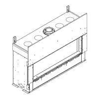
Figure 7.13 Place Outer Cover Plate on Top of Appliance
Figure 7.15 Plate on Top
• Place the outer cover plate and white gasket (removed in
Figure 7.7) on the appliance top. Use four screws to hold
the outer cover plate in place. See Figure 7.13.
Figure 7.14 Cover Plate
• Locate the cover plate removed in the fi rst step and place
on top of top pan heat shield. Place four screws to hold
this plate in place. See Figure 7.14.
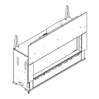
• Locate the back cover plate removed in Figure 7.6. Place
the plate on top of the appliance. See Figure 7.15. Use
four screws to hold this plate in place. See Figure 7.16.
Figure 7.16 Plate into place.
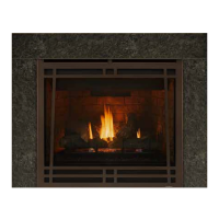
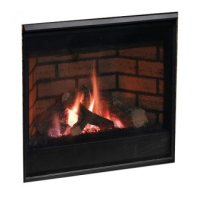
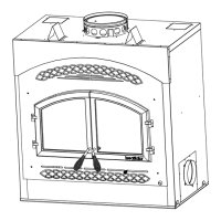
Figure 7.17 Completed Conversion
• The appliance should like the one shown in Figure 7.17
after it has been converted to a rear vented appliance.
 Loading...