63
3) Disconnect and label or draw a diagram of each wire connection
on the aquastat.
4) Loosen the two screws at the back of the aquastat, which clamp the
aquastat to the “well” in the water jacket.
5) Pull the aquastat body straight out of the “well”, ensuring the
copper wire and probe is being pulled out of the well along with the body.
6) Insert the new unit probe rst into the well. (Ensure contact paste has
been applied to well.)
7) The clamp must t around the groove of the well. Tighten the clamp
with the two screws at the back of the aquastat body.
8) Connect the electrical wires to the appropriate connections, following
the label or diagram.
9) Replace the cover.
10) Turn on the power.
11) Adjust the dial and white wheel to the preferred settings.
Front Light and Fan Power Switch
Principles
1) To provide light while fueling.
2) To provide a means of turning off the combustion air blowers on demand.
3) To provide a visual warning that electrical power to the combustion air
blowers has been terminated.
Operation of the Front Light and Fan Power Switch
• By adjusting the fan power switch to the down position, the electrical
power to the combustion air blower(s) is manually terminated, and the
front light turns on.
• This light will then illuminate the area in front of the HEATMOR™.
• The light must be turned off for electrical power to be running to the
combustion air blowers.
IF THE WATER TEMPERATURE IS HIGH ENOUGH TO TRIGGER THE HIGH WATER
TEMPERATURE SAFETY SHUTOFF, THE FRONT LIGHT WILL NOT TURN ON
WHEN THE FAN POWER SWITCH IS IN THE DOWN POSITION.
Removal and Replacement of the Front Light Bulb
1) Remove the glass globe by rst loosening the setscrew and then unscrew the globe.
2) Replace the light bulb.
3) Replace the globe and tighten the setscrew.
Removal and Replacement of the Fan Power/Light Switch
1) Turn off the main electrical power supply to the HEATMOR™.
2) Remove the switch cover plate.
3) Make a sketch of the location of the wires on the switch.
4) Remove the wires, and replace the switch. This is a special 3-way switch.
5) Replace the wires as in the diagram.
6) Secure the cover plate.
7) Turn the main electrical power supply back on to the HEATMOR™.
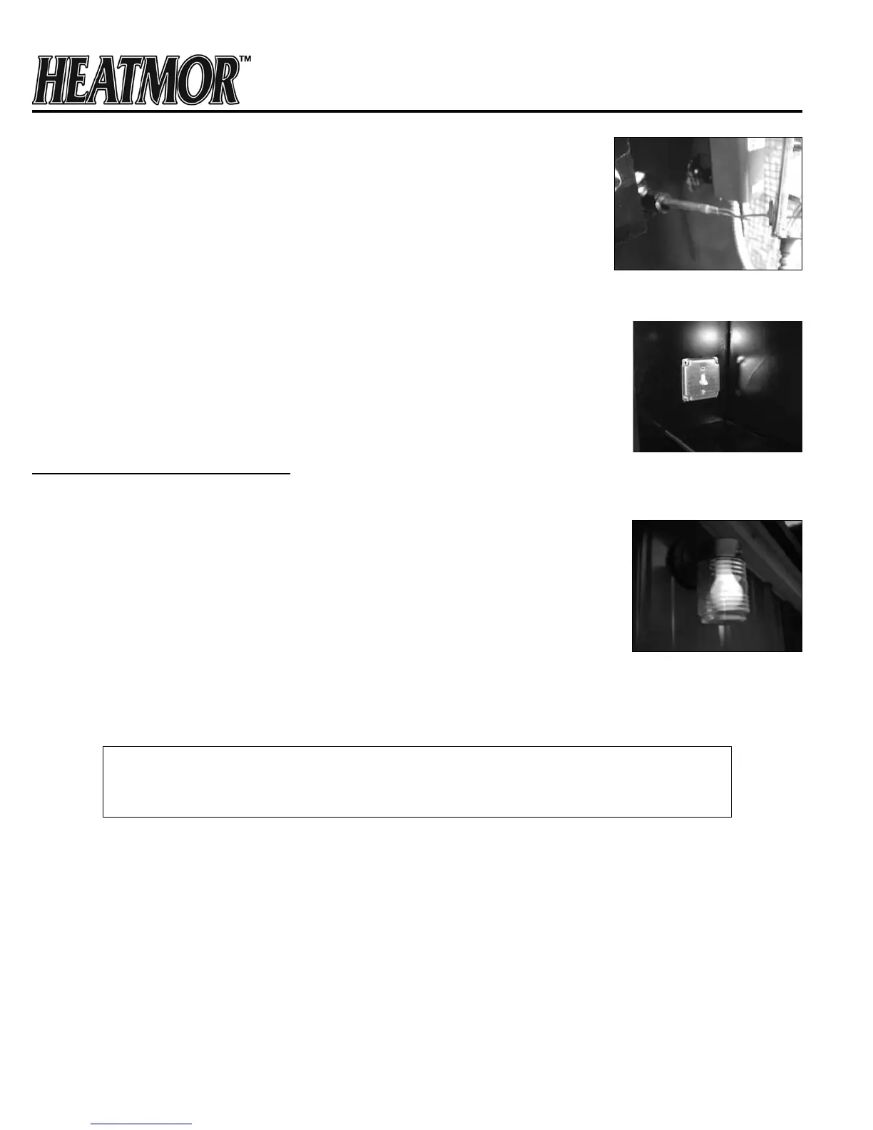
Wire Probe
Front Light and Fan
Power Switch
Front Light