10
441 01 2121 01
The minimum dimension of air openings shall be at
least 3 in. (80 mm). (See Figure 8)
c. Combining space on different floor levels. The
volumes of spaces on different floor levels shall be
considered as communicating spaces if connected
by one or more permanent openings in doors or
floors having free area of at least 2 in.
2
/1,000 Btuh
(4,400 mm
2
/kW) of total input rating of all gas appli-
ances.
2. An attic or crawlspace may be considered a space that
freely communicates with the outdoors provided there
are adequate permanent ventilation openings directly
to outdoors having free area of at least 1−in.
2
/4,000
Btuh of total input rating for all gas appliances in the
space.
3. In spaces that use the Indoor Combustion Air Meth-
od, infiltration should be adequate to provide air for
combustion, permanent ventilation and dilution of flue
gases. However, in buildings with unusually tight con-
struction, additional air MUST be provided using the
methods described in the Outdoor Combustion Air
Method section.
4. Unusually tight construction is defined as Construction
with:
a. Walls and ceilings exposed to the outdoors have a
continuous, sealed vapor barrier. Openings are gas-
keted or sealed and
b. Doors and openable windows are weatherstripped
and
c. Other openings are caulked or sealed. These in-
clude joints around window and door frames,
between sole plates and floors, between wall−ceil-
ing joints, between wall panels, at penetrations for
plumbing, electrical and gas lines, etc.
Combination of Indoor and Outdoor Air
1. Indoor openings shall comply with the Indoor Com-
bustion Air Method below and,
2. Outdoor openings shall be located as required in the
Outdoor Combustion Air Method mentioned previ-
ously and,
3. Outdoor openings shall be sized as follows:
a. Calculate the Ratio of all Indoor Space volume di-
vided by required volume for Indoor Combustion
Air Method below.
b. Outdoor opening size reduction Factor is 1 minus
the Ratio in a. above.
c. Minimum size of Outdoor openings shall be the size
required in Outdoor Combustion Air Method
above multiplied by reduction Factor in b. above.
The minimum dimension of air openings shall be
not less than 3 in. (80 mm).
INSTALLATION
UPFLOW INSTALLATION
Bottom Return Air Inlet
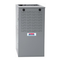
These furnaces are shipped with bottom closure panel
installed in bottom return−air opening. Remove and discard
this panel when bottom return air is used. To remove bottom
closure panel, perform the following:
1. Tilt or raise furnace and remove 2 screws holding bot-
tom filler panel. (See Figure 9)
2. Rotate bottom filler panel downward to release holding
tabs.
3. Remove bottom closure panel.
4. Reinstall bottom filler panel and screws.
Side Return Air Inlet
These furnaces are shipped with bottom closure panel
installed in bottom return−air opening. This panel MUST be in
place when only side return air is used.
Figure 9 − Removing Bottom Closure Panel
BOTTOM
FILLER PANEL
BOTTOM
CLOSURE
PANEL
NOTE: Side return−air openings can be used in UPFLOW
and most HORIZONTAL configurations. Do not use side
return−air openings in DOWNFLOW configuration.
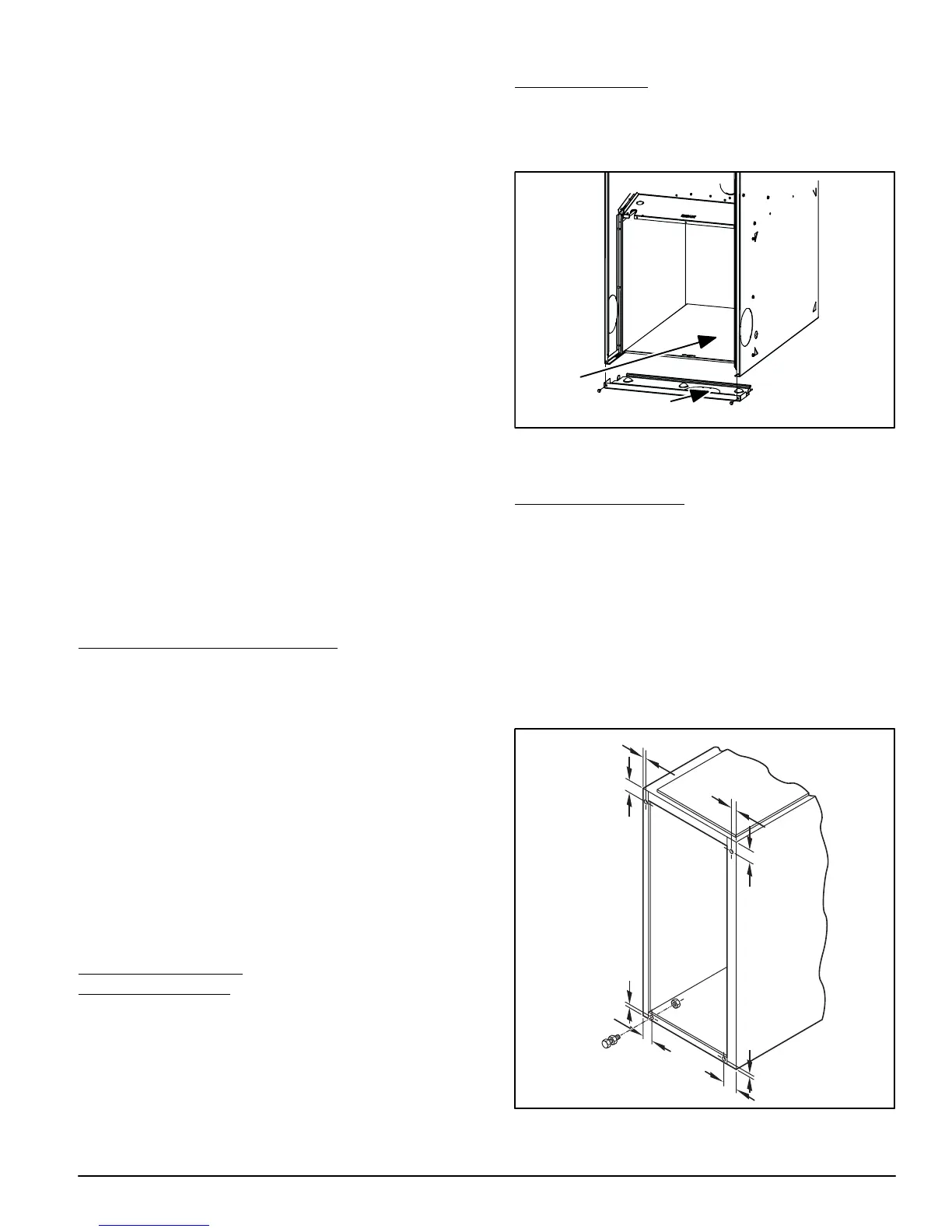
Leveling Legs (If Desired)
In upflow position with side return inlet(s), leveling legs may
be used. (See Figure 10) Install field−supplied, 5/16 X 1−1/2
in. (8 X 38 mm) (max) corrosion−resistant machine bolts,
washers and nuts.
NOTE: Bottom closure must be used when leveling legs are
used. It may be necessary to remove and reinstall bottom
closure panel to install leveling legs. To remove bottom
closure panel, see Item 1 in Bottom Return Air Inlet section in
Step 1 above.
To install leveling legs:
1. Position furnace on its back. Locate and drill a hole in
each bottom corner of furnace. (See Figure 10)
1
3
/
4
″
1
3
/
4
″
1
3/
4
″
1
3/
4
″
5/
16
″
5
/
16
″
5/
16
″
5/
16
″
(44mm)
(8mm)
(44mm)
(8mm)
(8mm)
(8mm)
(44mm)
(44mm)
A89014
2. For each leg, install nut on bolt and then install bolt with
nut in hole. (Install flat washer if desired.)