11
441 01 2121 01
3. Install another nut on other side of furnace base. (In-
stall flat washer if desired.)
4. Adjust outside nut to provide desired height, and tight-
en inside nut to secure arrangement.
5. Reinstall bottom closure panel if removed.
DOWNFLOW INSTALLATION
NOTE: For downflow applications, this furnace is approved
for use on combustible flooring when any one of the following
two accessories are used:
Downflow combustible floor subbase
Coil model numbers END4X or ENW4X
Coil casing model number NAEA
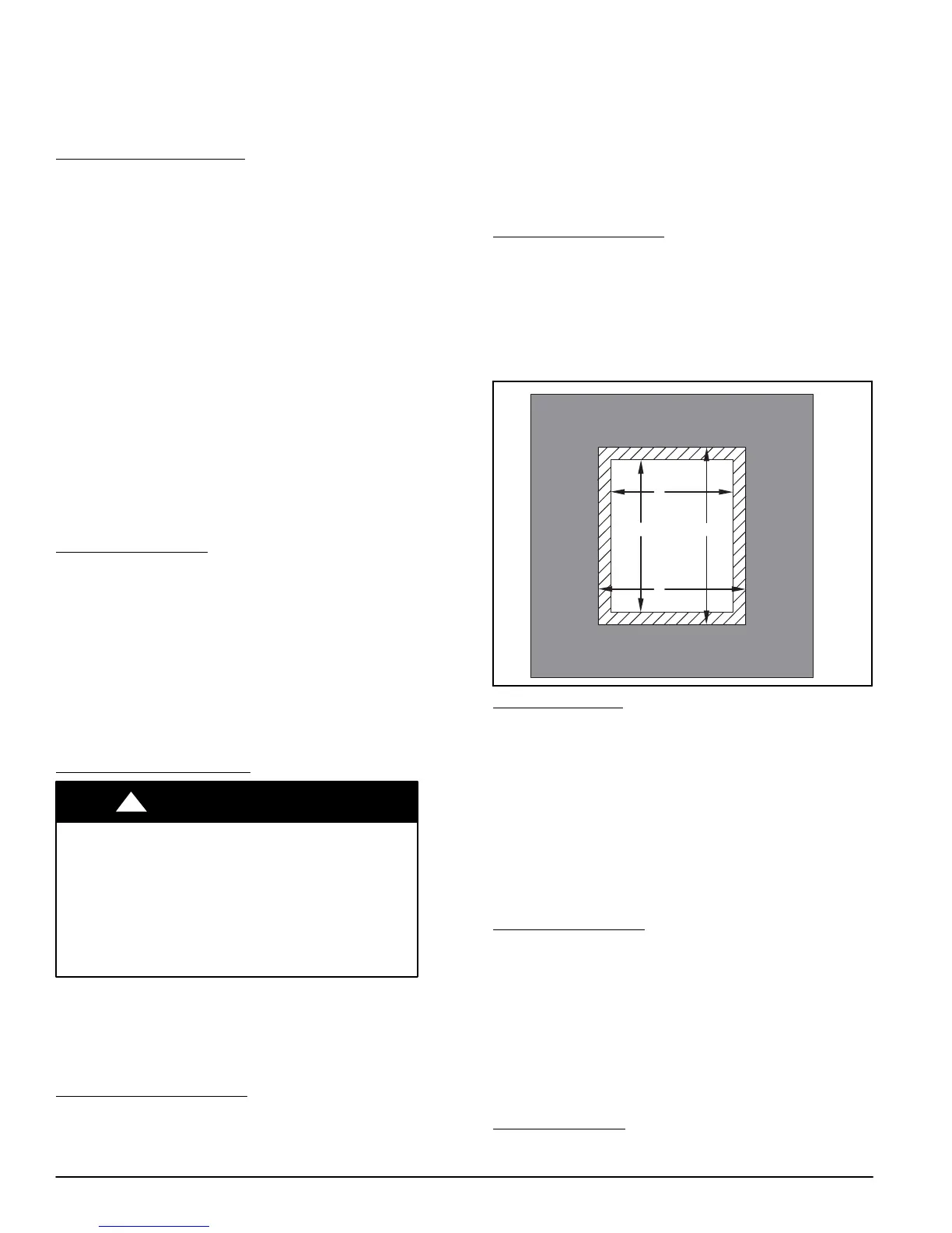
1. Determine application being installed from Table 4.
2. Construct hole in floor per Table 4 and Figure 11.
3. Construct plenum to dimensions specified in Table 4
and Figure 11.
4. If downflow subbase is used, install as shown in
Figure 12. If coil model numbers END4X, ENW4X or
coil casing model number NAEA are used, install as
shown in Figure 13.
NOTE: It is recommended that the perforated supply−air duct
flanges be completely folded over or removed from furnace
when installing the furnace on a factory−supplied cased coil
or coil casing. To remove the supply−air duct flange, use wide
duct pliers or hand seamers to bend flange back and forth
until it breaks off. Be careful of sharp edges. (See Figure 14)
Bottom Return Air Inlet
These furnaces are shipped with bottom closure panel
installed in bottom return−air opening. Remove and discard
this panel when bottom return air is used. To remove bottom
closure panel, perform the following:
1. Tilt or raise furnace and remove 2 screws holding bot-
tom filler panel. (See Figure 9)
2. Rotate bottom filler panel downward to release holding
tabs.
3. Remove bottom closure panel.
4. Reinstall bottom filler panel and screws.
Figure 10 − Leveling Legs
HORIZONTAL INSTALLATION
FIRE, EXPLOSION, AND CARBON MONOXIDE
POISONING HAZARD
Failure to follow this warning could result in personal
injury, death, or property damage.
Do not install the furnace on its back or hang furnace
with control compartment facing downward. Safety
control operation will be adversely affected. Never
connect return−air ducts to the back of the furnace.
!
WARNING
The furnace can be installed horizontally in an attic or
crawlspace on either the left−hand (LH) or right−hand (RH)
side. The furnace can be hung from floor joists, rafters or
trusses or installed on a non−combustible platform, blocks,
bricks or pad.
Suspended Furnace Support
The furnace may be supported under each end with threaded
rod, angle iron or metal plumber’s strap as shown. (See
Figure 15 and Figure 16) Secure angle iron to bottom of
furnace as shown. Heavy−gauge sheet metal straps
(plumber’s straps) may be used to suspend the furnace from
each bottom corner. To prevent screws from pulling out, use 2
#8 x in. screws into the side and 2 #8 x in. screws in the
bottom of the furnace casing for each strap. (See Figure 15
and Figure 16)
If the screws are attached to ONLY the furnace sides and not
the bottom, the straps must be vertical against the furnace
sides and not pull away from the furnace sides, so that the
strap attachment screws are not in tension (are loaded in
shear) for reliable support.
Platform Furnace Support
Construct working platform at location where all required
furnace clearances are met. (See Figure 3 and Figure 17) For
furnaces with 1−in. (25 mm) clearance requirement on side,
set furnace on non−combustible blocks, bricks or angle iron.
For crawlspace installations, if the furnace is not suspended
from the floor joists, the ground underneath furnace must be
level and the furnace set on blocks or bricks.
Figure 11 − Floor and Plenum Opening Dimensions
C
A
B D
A96283
Roll−Out Protection
Provide a minimum 17−3/4−in. X 22−in. (451 X 559 mm)
piece of sheet metal for flame roll−out protection in front of
burner area for furnaces closer than 12−in. (305 mm) above
the combustible deck or suspended furnaces closer than
12−in. (305 mm) to joists. The sheet metal MUST extend
underneath the furnace casing by 1−in. (25 mm)with the door
removed.
The bottom closure panel on furnaces of widths 17−1/2−in.
(445 mm) and larger may be used for flame roll−out
protection when bottom of furnace is used for return air
connection. See Figure 17 for proper orientation of roll−out
shield.
Bottom Return Air Inlet
These furnaces are shipped with bottom closure panel
installed in bottom return−air opening. Remove and discard
this panel when bottom return air is used. To remove bottom
closure panel, perform the following:
1. Tilt or raise furnace and remove two screws holding
bottom filler panel. (See Figure 9)
2. Rotate bottom filler panel downward to release holding
tabs.
3. Remove bottom closure panel.
4. Reinstall bottom filler panel and screws.
Side Return Air Inlet
These furnaces are shipped with bottom closure panel
installed in bottom return−air opening. This panel MUST be in