8
441 01 2121 01
Table 3 – Minimum Space Volumes for 100% Combustion, Ventilation, and Dilution from Indoors
OTHER THAN FAN‐ASSISTED TOTAL
(1,000'S BTUH GAS INPUT RATE)
FAN‐ASSISTED TOTAL
(1,000'S BTUH GAS INPUT RATE)
ACH
30 40 50 44 66 88 110 132
Space Volume Ft
3
(M
3
)
0.60 1,050 (29.7) 1,400 (39.6) 1,750 (49.5) 1,100 (31.1) 1,650 (46.7) 2,200 (62.2) 2,750 (77.8) 3,300 (93.4)
0.50 1,260 (35.6) 1,680 (47.5) 2,100 (59.4) 1,320 (37.3) 1,980 (56.0) 2,640 (74.7) 3,300 (93.4) 3,960 (112.1)
0.40 1,575 (44.5) 2,100 (59.4) 2,625 (74.3) 1,650 (46.7) 2,475 (70.0) 3,300 (93.4) 4,125 (116.8) 4,950 (140.1)
0.30 2,100 (59.4) 2,800 (79.2) 3,500 (99.1) 2,200 (62.2) 3,300 (93.4) 4,400 (124.5) 5,500 (155.7) 6,600 (186.8)
0.20 3,150 (89.1) 4,200 (118.9) 5,250 (148.6) 3,300 (93.4) 4,950 (140.1) 6,600 (186.8) 8,250 (233.6) 9,900 (280.3)
0.10 6,300 (178.3) 8,400 (237.8) 10,500 (297.3) 6,600 (186.8) 9,900 (280.3) 13,200 (373.7) 16,500 (467.2) 19,800 (560.6)
0.00 NP NP NP NP NP NP NP NP
NP = Not Permitted
AIR FOR COMBUSTION AND
VENTILATION
Provisions for adequate combustion, ventilation, and dilution
air must be provided in accordance with:
U.S. Installations: Section 9.3 of the NFPA 54/ANSI
Z223.1−2009 , Air for Combustion and Ventilation
and applicable provisions of the local building
codes.
FURNACE CORROSION HAZARD
Failure to follow this caution may result in furnace
damage.
Air for combustion must not be contaminated by halogen
compounds, which include fluoride, chloride, bromide,
and iodide. These elements can corrode heat
exchangers and shorten furnace life. Air contaminants
are found in aerosol sprays, detergents, bleaches,
cleaning solvents, salts, air fresheners, and other
household products.
CAUTION
!
CARBON MONOXIDE POISONING HAZARD
Failure to follow this warning could result in personal
injury or death.
The operation of exhaust fans, kitchen ventilation fans,
clothes dryers, attic exhaust fans or fireplaces could
create a NEGATIVE PRESSURE CONDITION at the
furnace. Make−up air MUST be provided for the
ventilation devices, in addition to that required by the
furnace. Refer to the Carbon Monoxide Poisoning Hazard
warning in the venting section of these instructions to
determine if an adequate amount of make−up air is
available.
!
WARNING
The requirements for combustion and ventilation air depend
upon whether or not the furnace is located in a space having
a volume of at least 50 cubic feet per 1,000 Btuh input rating
for all gas appliances installed in the space.
Spaces having less than 50 cubic feet per 1,000
Btuh require the OUTDOOR COMBUSTION AIR
METHOD.
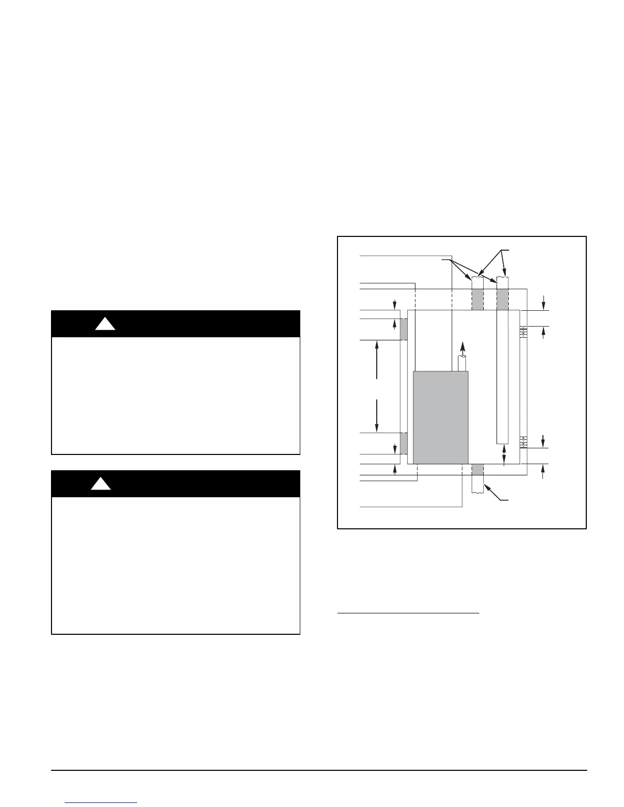
Figure 7 − Air for Combustion, Ventilation, and Dilution
for Outdoors
1 SQ IN .
PER
4000
BTUH*
DUCTS
TO
O UTDOORS
1 SQ IN.
PER 4000
BTUH*
C IRCULA TING
AIR DUCTS
VENT
THR OUGH
R OOF
D
B
A
C
E
1 SQ IN.
PER 4000
BTUH*
DUCT
TO
OUTDOORS
CIRCULA TING AIR DUCT S
1 SQ IN.
PER 2000
BTUH*
1 SQ IN.
PER 2000
BTUH*
DUCT S
TO
OUTDOORS
12 ″ MAX
12 ″ MAX
12 ″ MAX
12 ″
MAX
12 ″
MAX
OUTDOORS
1 SQ IN .
PER
4000
BTUH*
F
G
CLEARANCE IN FRONT
OF COMB USTION AIR
OPENINGS SHALL BE
AT LEAST 3 IN .
(305mm)
(305mm)
(305mm)
(305mm)
(305mm)
(76mm)
*Minimum dimensions of 3-in. (76 mm).
NOTE: Use any of the following combinations of openings:
A & B C & D D & E F & G
A03174
Spaces having at least 50 cubic feet per 1,000 Btuh
may use the INDOOR COMBUSTION AIR, STAND-
ARD or KNOWN AIR INFILTRATION METHOD.
Outdoor Combustion Air Method
1. Provide the space with sufficient air for proper combus-
tion, ventilation, and dilution of flue gases using per-
manent horizontal or vertical duct(s) or opening(s) dir-
ectly communicating with the outdoors or spaces that
freely communicate with the outdoors.
2. Figure 7 illustrates how to provide TWO OUTDOOR
OPENINGS, one inlet and one outlet combustion and
ventilation air opening, to the outdoors.
a. One opening MUST commence within 12 in. (300
mm) of the ceiling and the second opening MUST
commence within 12 in. (300 mm) of the floor.
b. Size openings and ducts per Figure 7 and Table 2.