21
441 01 2121 01
13. Reinstall cover to J−Box. Do not pinch wires between
cover and bracket.
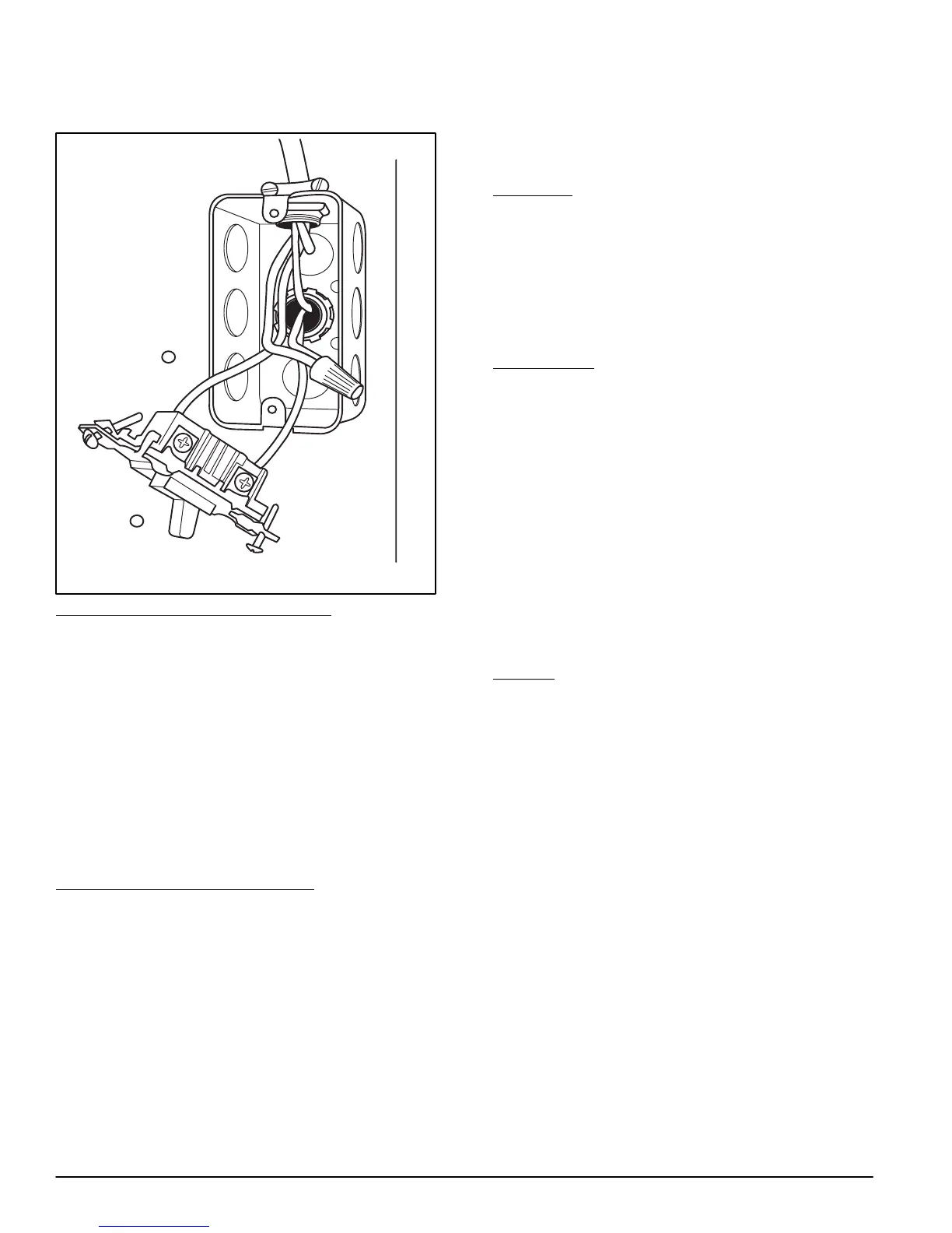
Figure 24 − Field−Supplied Electrical Box on Furnace
Casing
Power Cord Installation in Furnace J−Box
NOTE: Power cords must be able to handle the electrical
requirements listed in Table 6. Refer to power cord
manufacturer’s listings.
1. Remove cover from J−Box.
2. Route listed power cord through 7/8−in. (22 mm) dia-
meter hole in J−Box.
3. Secure power cord to J−Box bracket with a strain relief
bushing or a connector approved for the type of cord
used.
4. Secure field ground wire to green ground screw on
J−Box bracket.
5. Connect line voltage leads as shown in Figure 25.
6. Reinstall cover to J−Box. Do not pinch wires between
cover and bracket.
BX Cable Installation in Furnace J−Box
1. Remove cover from J−Box.
2. Route BX cable into 7/8−in. (22 mm) diameter hole in
J−Box.
3. Secure BX cable to J−Box bracket with connectors ap-
proved for the type of cable used.
4. Secure field ground wire to green ground screw on
J−Box bracket.
5. Connect line voltage leads as shown in Figure 25.
6. Reinstall cover to J−Box. Do not pinch wires between
cover and bracket.
24−V Wiring
Make field 24−v connections at the 24−v terminal strip. (See
Figure 25 − Figure 33) Connect terminal Y/Y2 as shown in
Figure 27−Figure 33 for proper cooling operation. Use only
AWG No. 18, color−coded, copper thermostat wire.
The 24−v circuit contains an automotive−type, 3−amp. fuse
located on the control. Any direct shorts during installation,
service, or maintenance could cause this fuse to blow. If fuse
replacement is required, use ONLY a 3−amp. fuse of identical
size.
ACCESSORIES
1. Electronic Air Cleaner (EAC)
Connect an accessory Electronic Air Cleaner (if used)
using 1/4−in female quick connect terminals to the two
male 1/4−in quick−connect terminals on the control
board marked EAC−1 and EAC−2. The terminals are
rated for 115VAC, 1.0 amps maximum and are ener-
gized during blower motor operation. (See Figure 26)
2. Humidifier (HUM)
Connect an accessory 24 VAC, 0.5 amp. maximum hu-
midifier (if used) to the 1/4−in male quick−connect HUM
terminal and COM−24V screw terminal on the control
board thermostat strip. The HUM terminal is energized
when blower is energized in heating. (See Figure 26)
NOTE: DO NOT connect furnace control HUM terminal to H
terminal on humidity sensing thermostat, or similar device.
See the humidity sensing thermostat, instructions for proper
connection.
VENTING
The furnace shall be connected to a listed factory built
chimney or vent, or a clay−tile lined masonry or concrete
chimney. Venting into an unlined masonry chimney or
concrete chimney is prohibited.
When an existing Category I furnace is removed or replaced,
the original venting system, may no longer be sized to
properly vent the attached appliances. An improperly sized
Category I venting system could cause the formation of
condensate in the furnace and vent, leakage of condensate
and combustion products, and spillage of combustion
products into the living space.