5
441 01 2121 01
General Installation
Current edition of the NFGC and the NFPA 90B. For copies,
contact the National Fire Protection Association Inc.,
Batterymarch Park, Quincy, MA 02269; (www.NFPA.org) or
for only the NFGC, contact the American Gas Association,
400 N. Capitol Street, N.W., Washington, DC 20001
(www.AGA.org) .
Combustion and Ventilation Air
Section 9.3 NFPA 54/ANSI Z223.1−2009 , Air for Combustion
and Ventilation .
Duct Systems
Air Conditioning Contractors Association (ACCA) Manual D,
Sheet Metal and Air Conditioning Contractors National
Association (SMACNA), or American Society of Heating,
Refrigeration, and Air Conditioning Engineers (ASHRAE)
2001 Fundamentals Handbook Chapter 34 or 2000 HVAC
Systems and Equipment Handbook Chapters 9 and 16.
Acoustical Lining and Fibrous Glass Duct
Current edition of SMACNA and NFPA 90B as tested by UL
Standard 181 for Class I Rigid Air Ducts
Gas Piping and Gas Pipe Pressure Testing
NFPA 54/ANSI Z223.1−2009 ; chapters 5, 6, and 7 and
National Plumbing Codes .
Electrical Connections
National Electrical Code (NEC) ANSI/NFPA70−2008 .
Venting
NFPA 54/ANSI Z223.1−2009; chapters 12 and 13.
ELECTROSTATIC DISCHARGE (ESD)
PRECAUTIONS PROCEDURE
FURNACE RELIABILITY HAZARD
Failure to follow this caution may result in unit component
damage.
Electrostatic discharge can affect electronic components.
Take precautions during furnace installation and
servicing to protect the furnace electronic control.
Precautions will prevent electrostatic discharges from
personnel and hand tools which are held during the
procedure. These precautions will help to avoid exposing
the control to electrostatic discharge by putting the
furnace, the control, and the person at the same
electrostatic potential.
CAUTION
!
1. Disconnect all power to the furnace. Multiple discon-
nects may be required. DO NOT TOUCH THE CON-
TROL OR ANY WIRE CONNECTED TO THE CON-
TROL PRIOR TO DISCHARGING YOUR BODY’S
ELECTROSTATIC CHARGE TO GROUND.
2. Firmly touch the clean, unpainted, metal surface of the
furnace chassis which is close to the control. Tools
held in a person’s hand during grounding will be satis-
factorily discharged.
3. After touching the chassis, you may proceed to service
the control or connecting wires as long as you do noth-
ing to recharge your body with static electricity (for ex-
ample; DO NOT move or shuffle your feet, do not touch
ungrounded objects, etc.).
4. If you touch ungrounded objects (and recharge your
body with static electricity), firmly touch a clean, un-
painted metal surface of the furnace again before
touching control or wires.
5. Use this procedure for installed and uninstalled (un-
grounded) furnaces.
6. Before removing a new control from its container, dis-
charge your body’s electrostatic charge to ground to
protect the control from damage. If the control is to be
installed in a furnace, follow items 1 through 4 before
bringing the control or yourself in contact with the fur-
nace. Put all used and new controls into containers be-
fore touching ungrounded objects.
7. An ESD service kit (available from commercial
sources) may also be used to prevent ESD damage.
LOCATION
GENERAL
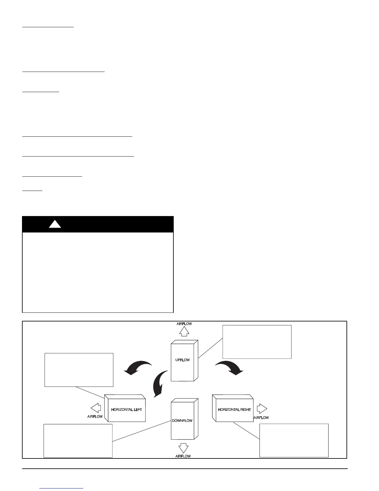
This multipoise furnace is shipped in packaged configuration.
Some assembly and modifications are required when used in
any of the four applications shown in Figure 4.
NOTE: For high−altitude installations, the high−altitude
conversion kit MUST be installed at or above 5500 ft. (1676
M) above sea level. Obtain high−altitude conversion kit from
your area authorized distributor.
Figure 4 − Multipoise Orientations
THE BLOWER IS LOCATED
TO THE RIGHT OF THE
BURNER SECTION, AND
AIR CONDITIONED AIR IS
DISCHARGED TO THE LEFT.
THE BLOWER IS
LOCATED BELOW THE
BURNER SECTION, AND
CONDITIONED AIR IS
DISCHARGED UPWARD.
THE BLOWER IS
LOCATED ABOVE THE
BURNER SECTION, AND
CONDITIONED AIR IS
DISCHARGED DOWNWARD
THE BLOWER IS
LOCATED TO THE LEFT
OF THE BURNER SECTION,
AND CONDITIONED AIR IS
DISCHARGED TO THE RIGHT.
A02097