19
441 01 2121 01
psig (14−In. W.C.) stated on gas control valve. (See
Figure 49)
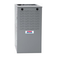
Some installations require gas entry on right side of furnace
(as viewed in upflow). (See Figure 21)
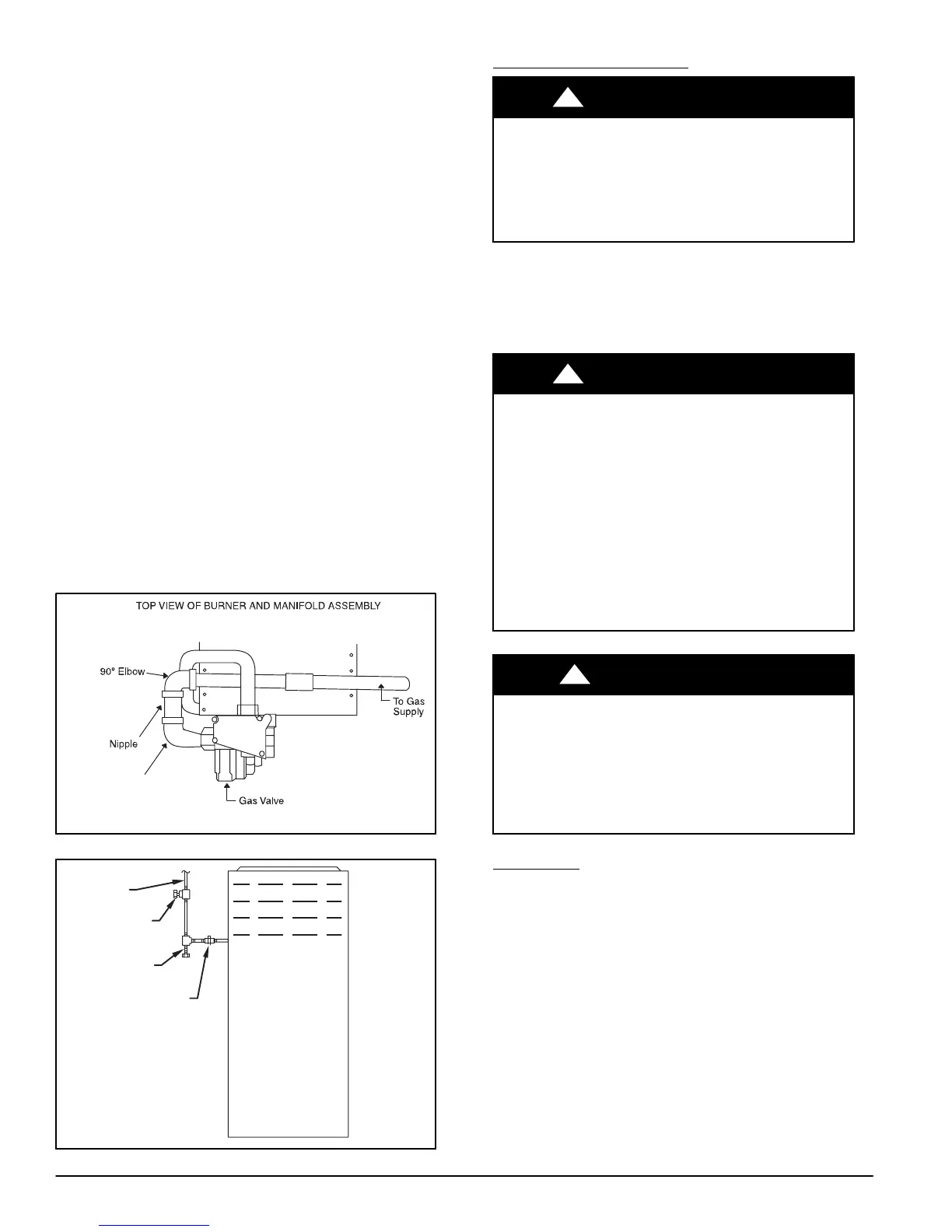
Install a sediment trap in riser leading to furnace as shown in
Figure 22. Connect a capped nipple into lower end of tee.
Capped nipple should extend below level of furnace gas
controls. Place a ground joint union between furnace gas
control valve and exterior manual equipment gas shutoff
valve.
A 1/8−in. (3 mm) NPT plugged tapping, accessible for test
gauge connection, MUST be installed immediately upstream
of gas supply connection to furnace and downstream of
manual equipment shutoff valve.
Piping should be pressure and leak tested in accordance with
the current addition of the NFGC in the United States, local,
and national plumbing and gas codes before the furnace has
been connected. After all connections have been made,
purge lines and check for leakage at furnace prior to
operating furnace.
If pressure exceeds 0.5 psig (14−In. W.C.), gas supply pipe
must be disconnected from furnace and capped before and
during supply pipe pressure test. If test pressure is equal to or
less than 0.5 psig (14−In. W.C.), turn off electric shutoff switch
located on furnace gas control valve and accessible manual
equipment shutoff valve before and during supply pipe
pressure test. After all connections have been made, purge
lines and check for leakage at furnace prior to operating
furnace.
The gas supply pressure shall be within the maximum and
minimum inlet supply pressures marked on the rating plate
with the furnace burners ON and OFF.
Figure 21 − Burner and Manifold
2” (51mm)
Street Elbow
A08551
Figure 22 − Typical Gas Pipe Arrangement
UNION
SEDIMENT
TRAP
MANUAL
SHUTOFF
VALVE
(REQUIRED)
GAS
SUPPLY
A02035
ELECTRICAL CONNECTIONS
ELECTRICAL SHOCK HAZARD
Failure to follow this warning could result in personal
injury or death.
Blower access panel door switch opens 115−v power
to control. No component operation can occur. Do not
bypass or close switch with panel removed.
!
WARNING
See Figure 24 for field wiring diagram showing typical field
115−v wiring. Check all factory and field electrical
connections for tightness.
Field−supplied wiring shall conform with the limitations of
63F (33C) rise.
ELECTRICAL SHOCK AND FIRE HAZARD
Failure to follow this warning could result in personal
injury, death, or property damage.
The cabinet MUST have an uninterrupted or
unbroken ground according to NEC ANSI/NFPA
70−2008 or local codes to minimize personal injury if
an electrical fault should occur. This may consist of
electrical wire, conduit approved for electrical ground
or a listed, grounded power cord (where permitted by
local code) when installed in accordance with existing
electrical codes. Refer to the power cord
manufacturer’s ratings for proper wire gauge. Do not
use gas piping as an electrical ground.
!
WARNING
FURNACE MAY NOT OPERATE HAZARD
Failure to follow this caution may result in intermittent
furnace operation.
Furnace control must be grounded for proper
operation or else control will lock out. Control must
remain grounded through green/yellow wire routed to
gas valve and manifold bracket screw.
CAUTION
!
115−V Wiring
Verify that the voltage, frequency, and phase correspond to
that specified on unit rating plate. Also, check to be sure that
service provided by utility is sufficient to handle load imposed
by this equipment. Refer to rating plate or Table 7 for
equipment electrical specifications.
U.S. Installations: Make all electrical connections in
accordance with National Electrical Code (NEC) ANSI/NFPA
70−2008 and any local codes or ordinances that might apply.