2
441 01 2121 01
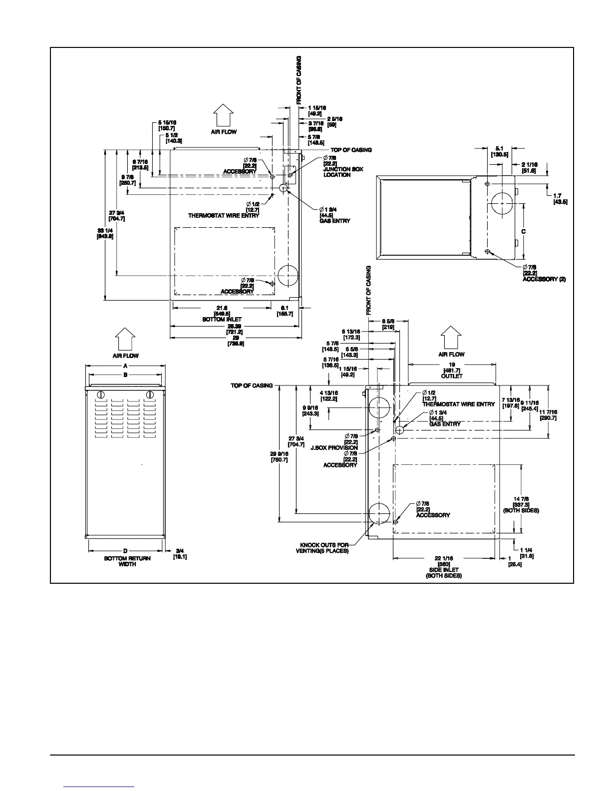
Figure 1 − Dimensional Drawing
NOTES:
1. Two additional 7/8-in. (22 mm) diameter holes are located in the top plate.
2. Minimum return-air openings at furnace, based on metal duct. If flex duct is used, see flex duct manufacturer's recommendations for equivalent diameters.
a. For 800 CFM-16-in. (406 mm) round or 14 1/2 x 12-in. (368 x 305 mm) rectangle.
b. For 1200 CFM-20-in. (508 mm) round or 14 1/2 x 19 1/2-in. (368 x 495 mm) rectangle.
c. For 1600 CFM-22-in. (559 mm) round or 14 1/2 x 22 1/16-in. (368 x 560mm) rectangle.
d. For airflow requirements above 1800 CFM, see Air Delivery table in Product Data literature for specific use of single side inlets. The use of both side inlets, a
combination of 1 side and the bottom, or the bottom only will ensure adequate return air openings for airflow requirements above 1800 CFM.
Table 1 – Dimensions − In. (mm)
FURNACE SIZE
A B C E VENT
CABINET
WIDTH
IN. (mm)
OUTLET
WIDTH
IN. (mm)
TOP AND BOTTOM
FLUE COLLAR
IN. (mm)
BOTTOM INLET
WIDTH
IN. (mm)
CONNECTION
SIZE
IN. (mm)
SHIP WT.
LB (KG)
0701412 14−3/16 (360) 12−9/16 (319) 9−5/16 (237) 12−11/16 (322) 4 (102) 115 (52)
0901716 17−1/2 (445) 15−7/8 (403) 11−9/16 (294) 16 (406) 4 (102) 130 (59)
1102120 21 (533) 19−3/8 (492) 13−5/16 (338) 19−1/2 (495) 4 (102) 155 (70)
1352422 24−1/2 (622) 22−7/8 (581) 15−1/16 (383) 23 (584) 4 (102)* 166 (75)
* 135 size furnace require a 5 in. or 6 in. (127 or 152 mm) vent. Use a vent adapter between furnace and vent stack.