12
Parker Hannifin Corporation
Helac/Cylinder Division
Enumclaw, Washington USA
www.helac.com
Helical, Hydraulic Rotary Actuators
L20 Series Service & Repair Manual
Catalog HY34-1120
Disassembly
Disassembly
8. Remove the stop tube (400) if the
actuator is equipped with one. The stop
tube is an available option that limits the
rotation of the actuator.
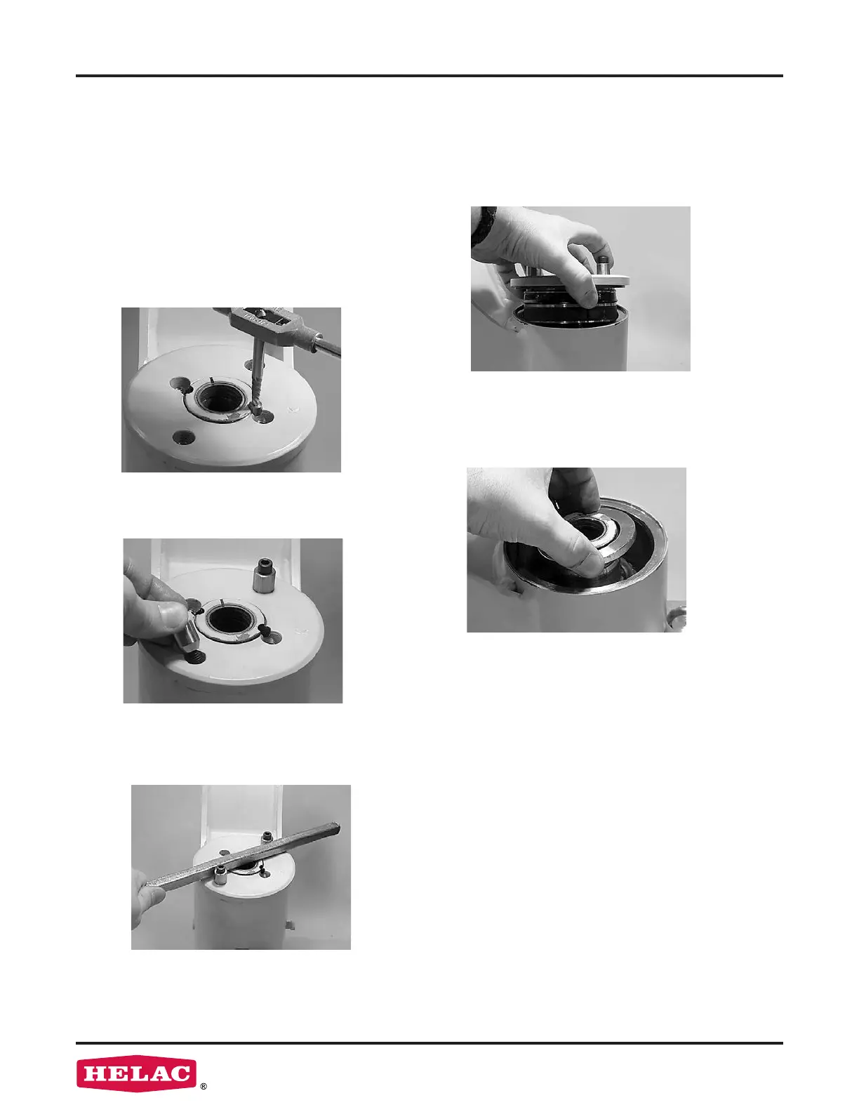
6.
Using a metal bar or similar tool, unthread
the end cap (04) by turning it counter-
clockwise.
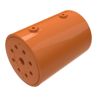
4. Remove the lock pins using a screw
extracting tool such as an Easy Out
TM
(a
size #2 is shown).
If the pin cannot be removed with the
screw extractor, use a 5/16” bit to drill out
the entire pin. Do not drill deeper than 1/2”
(12.7 mm).
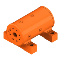
5. Install the end cap removal tools provided
with the Helac seal kit. (
1
/
4
-20)
7.
Remove the end cap (04) and carefully
set aside for later inspection.
 Loading...