13
Parker Hannifin Corporation
Helac/Cylinder Division
Enumclaw, Washington USA
www.helac.com
Helical, Hydraulic Rotary Actuators
L20 Series Service & Repair Manual
Catalog HY34-1120
Disassembly
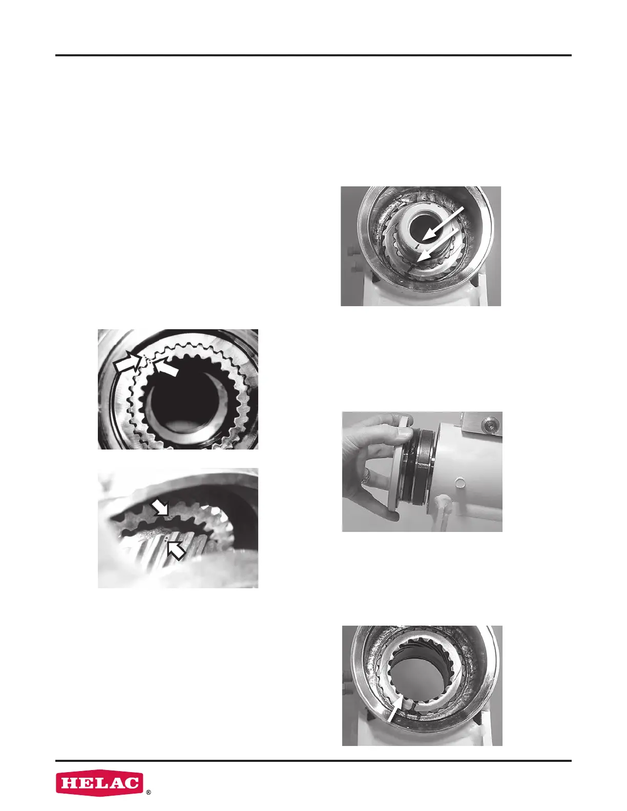
Disassembly
10. Prior to removing the shaft (02), use a
felt marker to clearly indicate the timing
between shaft and piston sleeve (03).
This will greatly simplify timing when the
actuator is reassembled.
9.
Every actuator has two sets of small
punched timing marks that indicate timing
between the gear sets. The location and
appearance of the marks can vary slightly
between models. One set indicates the
timing between the piston sleeve (03) and
the housing (01) (photo at left), the
second set between the piston and the
shaft (lower photo). To ensure correct
rotation and accurate end positions, it is
essential that the actuator be
correctly timed when it is reassembled.
The punched timing marks can be used,
but it is easier to highlight punched marks
with a marker before disassembly as
outlined in the steps below.
12.
As in step 9 above, before removing
the piston (03), mark the housing (01)
ring gear in relation to the piston outside
diameter gear. There should now be
timing marks on the housing (01) ring
gear, the piston (03) and the shaft (02).
11.
Remove the shaft (02) by rotating
counterclockwise. As the shaft is rotated,
it will disengage from the piston sleeve
(03) and can be removed. It may be
necessary to strike the threaded end of
the shaft with a rubber mallet.
 Loading...