59
The flow regulator serving both as a flow regulating valve while forks are being
lowering and a safety device if hoses between the control valve and lift cylinders are
damaged due to any reason.
The operation of the flow regulator valve is given below:
See Fig.9-2,With the forks upraised,high pressure oil leads from the control
valve then flows into the chamber A, and pushes the sleeve to the left. This opens the
opening B, and allows the high pressure oil to flow along the two routes(ACBF and
ACDF), and both flows of oil lead to the lift cylinders. In this case, the flows of oil is
not regulated. When the forks or the spenders begin to descend, oil discharged off the
lift cylinders enters the chamber F and pushes the sleeve to the right until it contacts
the nipple. This closes the opening D, so that oil flows through F,B,C and A to the
tank. If the flows of oil discharged off the lift cylinders is rapidly increased, the
pressure in the chamber F rises, and moves the piston to the right in spite of the spring
force,narrowing the opening B. So the flow of oil from the chamber B to the chamber
C is decreased so that the descending speed of the forks is controlled.
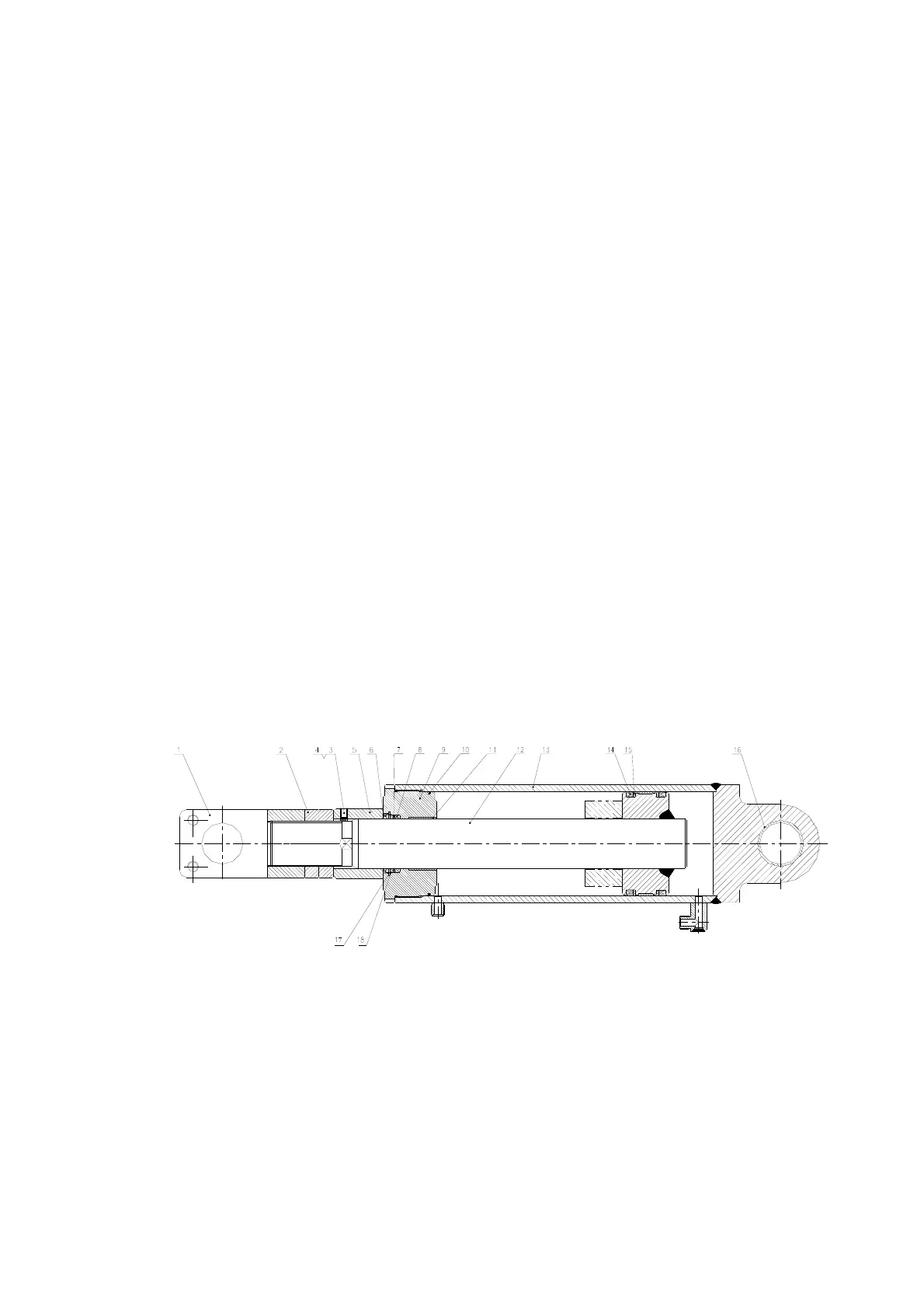
9.7 Tilt cylinder
(1)Ear ring (2)Adjust nut (3)Screw (4)Plug
(5)Spacer (6)Seal dust (7)Snap ringⅡ (8)Yx-ring
(9)Guide Sleeve (10)O-ring (11)Bushing (12)Body, piston ass’y
(13) Tube, cylinder ass’y (14)Yx-ring (15)Wearing
(16)Bushing (17)Snap ring (18)Snap ringⅠ
Fig.9-3 Tilt Cylinder