37
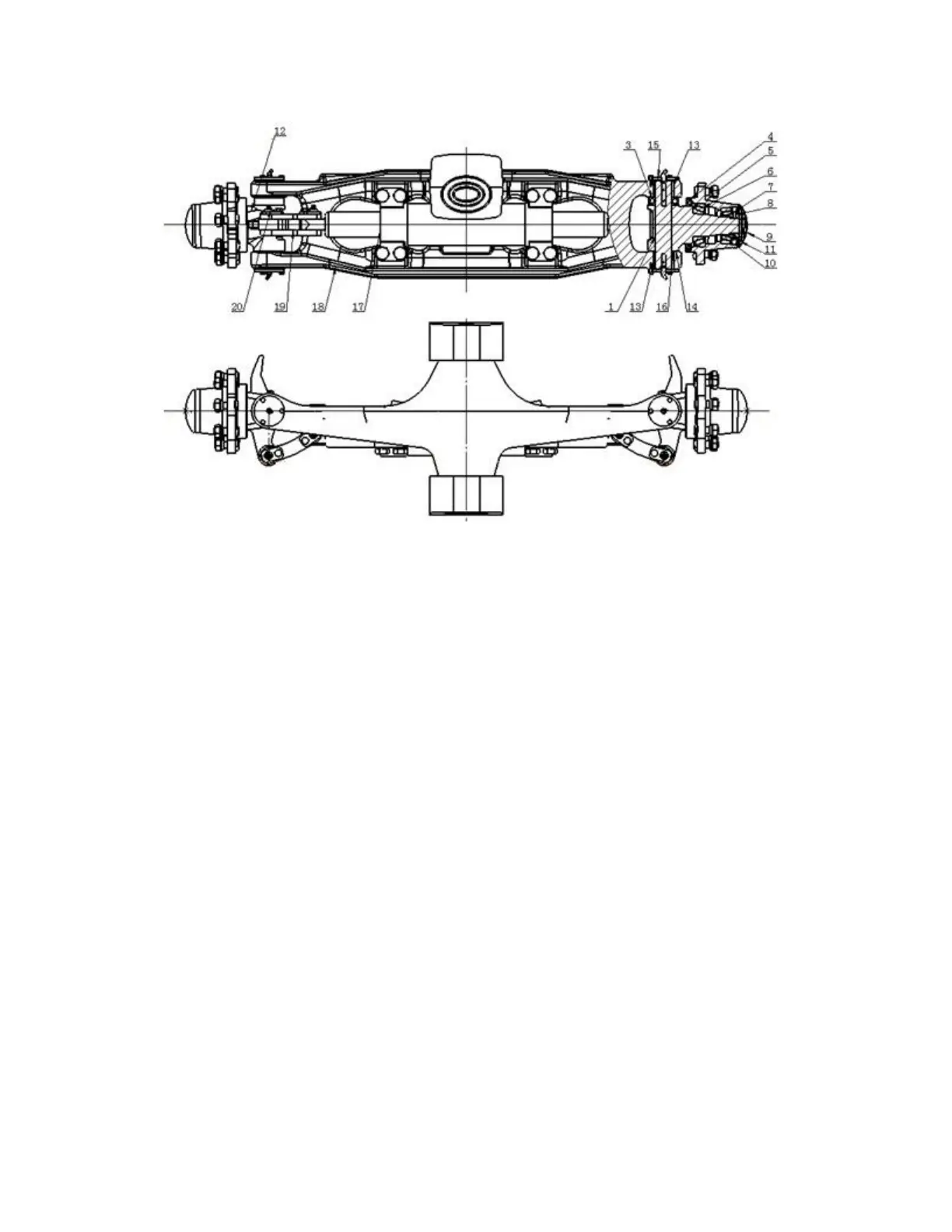
Figure 3-2 steering axle
(1) steering knuckle main pin (2) needle bearing (3) thrust bearing (4) oil seal
(5) Steering hub (6) tapered roller bearing (7) washer (8) lock nut
(9) hub cover (10) tapered roller bearing (11) pin (12) steering knuckle
(13) needle bearing (14) adjusting shim (15) oil seal (16) seal ring
(17) steering cylinder (18) steering axle body (19) link rod (20) pin axle
1) Steering knuckle
Both steering knuckles are fitted between the upper and the lower steering axle body
through two king pins, thrust bearings, needle bearings, dust covers and seal rings. The
king pin is locked on the steering knuckle with a lock pin. The upper end of the knuckle
is supported on the steering axle body by thrust bearing. Both ends of the king pin are
supported on the steering axle body by needle bearing. (See Fig. 3-3)