JS07N·JS07·JS08·JS12·JS14
51
Maintenance
The hydraulic tank is a vented-type tank. The
breather cap has an internal air filter that can
become clogged or, over time, can deteriorate.
If the breather cap is faulty or improperly in-
stalled, impurities can enter the hydraulic sys-
tem which may cause component damage. Ex-
tremely dirty conditions may require that the
cap be inspected more often.
1. Remove and discard the hydraulic tank
breather cap.
2. Install the new cap onto the tank.
Checklist D
D-1
Check the Scissor Arm Wear Pads
This procedure should be performed every
1000 hours or annually, whichever comes first.
Maintaining the condition of the scissor arm
wear pads is essential to safe machine opera-
tion. Continued use of worn out wear pads may
result in component damage and unsafe oper-
ating conditions.
Perform this procedure with the machine on a
firm, level surface that is free of obstructions.
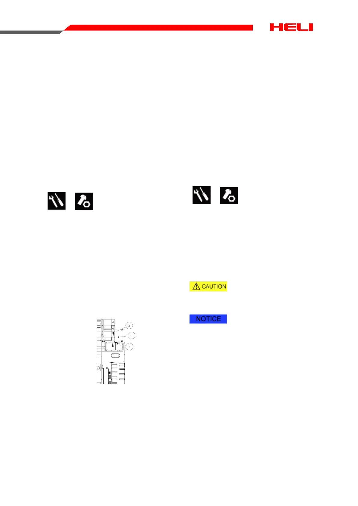
1. Measure the distance between the num-
ber one inner arm cross tube and the
chassis deck at the ground controls side of
the non-steer end of the machine.
a. inner arm cross tube
b. wear pad
c. chassis deck
Result: The measurement is not less than ⊙
x mm.(ZS07:x=34.5,ZS12:x=38) Refer to
Step2.
¤ Result: The measurement is less than x
mm. Replace the Scissor Arm Wear Pads
2. Measure the distance between the num-
ber one inner arm cross tube and the
chassis deck at the battery pack side of
the non-steer end of the machine.
Result: The measurement is not less than⊙
x mm. Refer to Step 3.
¤Result: The measurement is less than x
mm. Replace the Scissor Arm Wear Pads
3. Apply a thin layer of dry film lubricant to
the area of the chassis where the scissor
arm wear pads make contact.
D-2
Replace the Hydraulic Tank Return
Filter Element
This procedure should be performed every
1000 hours or annually, whichever comes first.
Replacement of the hydraulic tank return filter
is essential for good machine performance and
service life. A dirty or clogged filter may cause
the machine to perform poorly and continued
use may cause component damage. Ex-
tremely dirty conditions may require that the fil-
ter be replaced more often.
Scalding danger
Beware of hot oil Contact with hot oil may
cause severe burns.
The hydraulic tank return filter
is mounted on the function manifold next to
the hydraulic power unit.
1. Clean the area around the oil filter. Re-
move the filter with an oil filter wrench.
2. Apply a thin layer of oil to the new oil filter
gasket.
3. Install the new filter and tighten it securely
by hand.
4. Use a permanent ink marker to write the
date and number of hours from the hour
meter onto the filter
5. Turn the key switch to ground control and
pull out the red Emergency Stop button to
the on position at both the ground and
platform controls.
 Loading...