6.3 Electrical connection / commissioning
m
Touching live parts will lead to electric shock.
Isolate the unit from the mains power supply before connection!
m
Waiting time at least 5 minutes!
When using capacitors, there is danger to life after deactivation due to the direct touching of live
parts. Terminal compartment access is only permitted after power supply is disconnected and 5 minute wai-
ting period.
m WARNING!
The rotating impeller can crush fingers.
Ensure protection against contact before commissioning!
– The electrical connection and initial start-up must only be carried out by qualified electricians
according to the information in the attached wiring diagrams.
– All relevant standards, safety regulations (e.g. DIN VDE 0100), as well as the technical connection conditions of
energy suppliers are to be adhered to!
– A multipole mains section switch/isolator, with a minimum contact opening of 3 mm (VDE 0700 T1 7.12.2/
EN 60335-1) is mandatory!
– Network configuration, voltage and frequency must be consistent with the rating plate information.
– Check the waterproofing of the connection cable and tight clamping of the strands
– Metal cable screws must not be used when connecting to plastic terminal boxes.
– Insert the supply line so that no water can get in along the cable in case of water exposure.
– Check designated use of fan
– Compare mains voltage to rating plate data
– Check fan for solid mounting and professional electrical installation
– Check all parts for tightness, particularly screws, protection guards. Do not loosen screws in the process!
– Check free movement of the impeller.
Wear protective gloves when checking unhindered running of impeller!
– When the impeller is turned by hand, there will be slight resistance due to the permanent magnets.
This is for technical reasons and it is not a malfunction.
– Compare power consumption to rating plate data
– Check protective conductor connection
If a residual current device is installed in the supply line of the EC fan, the residual current device must have the following
technical features:
Type A or B with a rated differential current of 30 mA.
The EC fan has a leakage current of <= 3.5 mA, calculated according to DIN EN 50178 image 4.
6.4 Operation
In order to ensure the proper functioning of the fan, the following must be checked regularly:
– Formation of dust or dirt deposits in the casing or on the motor and impeller
– Freewheeling of impeller. Wear protective gloves when checking freewheeling of impeller!
– Occurrence of excessive vibration and noise
If excessive vibration or noise occurs, maintenance must be carried out according to the instructions in chapter 8.
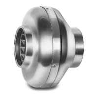
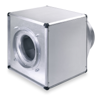
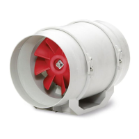
Centrifugal In-line EC Duct Fans – RR EC
Installation and Operating Instructions
Wand
Wall
Mur
ò
ù
4x Bohrschrauben
4x Self-tapping screws
4x vis autoforeuses
Montagekonsole für Wand oder Deckenmontage
Mounting rail for wall or ceiling suspension
Rail support pour montage au mur ou au plafond
Winkel
Bracket
Console
V
Schraubenposition V, je nach
Baugröße des Ventilators wählen.
Screw position V, choose depending
on the size of the fan.
Position des vis V, à déterminer
selon taille du ventilateur.
schraffierter Bereich:
hatched area:
Zone hachurée:
- Montagezone für Winkel
- Assembly area for
bracket
- Zone de montage
pour console
ù
ò
Fig.4
m
WARNING
m
WARNING
nmr
6
m
WARNING
m
WARNING
n
EN
 Loading...