77
Centrifugal In-line EC Duct Fans – RR EC
Installation and Operating Instructions
7.0 Functional description RR EC
The centrifugal in-line fans RR EC are steplessly speed-controllable by means of 0-10 V control voltage. Suitable poten-
tiometers (Type PU/A 10; SS-980-1), three-step switches (Type SU/A) are offered in the Helios accessories range.
Stepless speed control is possible with the universal controller (Type EUR EC; SS-1275). Alternatively, the electronic
differential pressure/temperature controller EDR / ETR can be used.
m
A minimum speed/voltage, which also depends on on-site resistances, wind pressure, etc., must be obser-
ved for sufficient motor cooling and ensuring proper functioning.
The use of other brands, especially other electronic devices, can lead to malfunctioning and even destruction of the
controller or fan. Controllers which have not been cleared by Helios are not liable for warranty and guarantee claims.
Activation / deactivation:
EC fans can be frequently activated and deactivated via the 0-10 V control input or the release input depending on the
type. This is gentle on the electronics and ensures a long service life. Control via the power supply (on/off) is not recom-
mended. In general, there must be an interval of at least 120 seconds between activation and deactivation.
Controlling multiple EC fans with a potentiometer
In order to control multiple EC fans above the setpoint input “0-10 V”, the 10 V DC voltage source must supply the
sum of all setpoint input load currents.
m
The parallel switching of +10 V DC power supplies for multiple EC fans is not permitted!
Depending on the type, multiple EC fans can be controlled with the 10 V DC power supply from one fan with
a potentiometer (PU/A). In this respect, consult the technical data for the control inputs and the wiring diagram
SS-1035. If the EC power supply current is not sufficient, a sufficient (customer-supplied) 10 V DC may be used (galva-
nically isolated from the mains power supply). Alternatively, the “EUR EC” module from Helios can be used for various
control tasks.
7.1 Wiring diagram overview
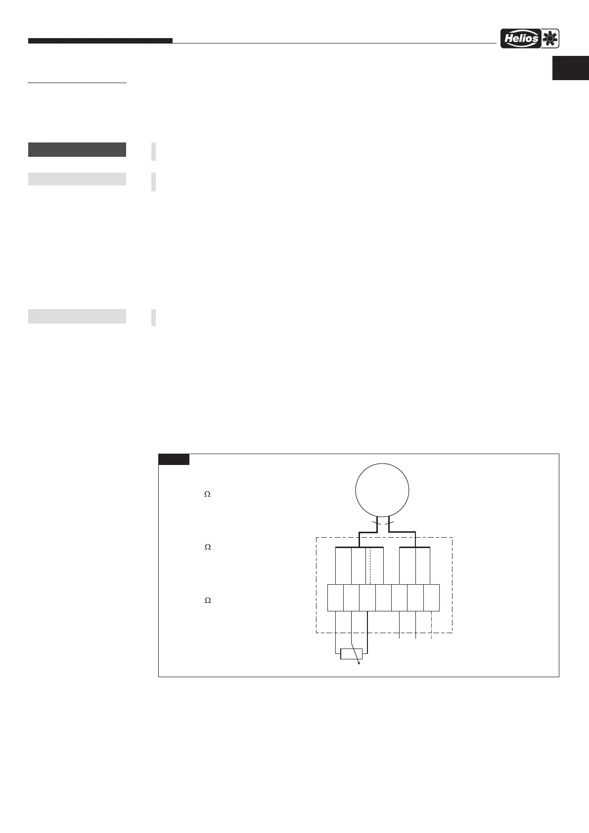
The allocated wiring diagram SS-979 must be observed (see Fig. 5). If stepless speed control takes place via the
speed-poteniometer PU/A 10, wiring diagram SS-980-1 must be observed (see Fig.6). Furthermore, the RR EC series
can be operated with the universal controller EUR EC (Ref. no. 01347) (refer to connection example Fig. 7).
7.1.1 Wiring diagram SS-979
SS-979
Fig.5
3
10V
YEGN
BN
YE
PE
L1
N
Klemmkasten
Terminal box
Boîte à bornes
EC-Motor
EC motor
Moteur EC
BU
85187 001 SS-979 14.12.17
10k
bauseits zu stellen bzw.
0-10V Signal von z.B.
PU/A 10 Art.Nr. 1734/1735
oder EUR EC Art. Nr. 1347
Potentiometer
M
EC
ADJ
GND
A1
L
N
PE
WH
BK/GY, BU
OG, RD
4
+10V
0-10V
(5)
10k
installed by the customer or
0-10V Signal from e.g.
PU/A 10 Art.Nr. 1734/1735
or EUR EC Art. Nr. 1347
Potentiometer
10k
instellé par le client ou
0-10V Signal par example d`un
PU/A 10 Art.Nr. 1734/1735
ou EUR EC Art. Nr. 1347
Potentiomètre
CHAPTER 7
FUNCTION FOR
INSTALLER
m
CAUTION
m
NOTE
m
NOTE
RR EC 100
RR EC 125
RR EC 160
RR EC 200 A
RR EC 200 B
RR EC 250 A
RR EC 250 B
RR EC 315 A
RR EC 315 B
EN
 Loading...