9
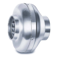
Centrifugal In-line EC Duct Fans – RR EC
Installation and Operating Instructions
PU/A 10
3
2
4
1
Potentiometer
min. rotational speed
7
6
5
LED 1
LED 2
S 1
R 1
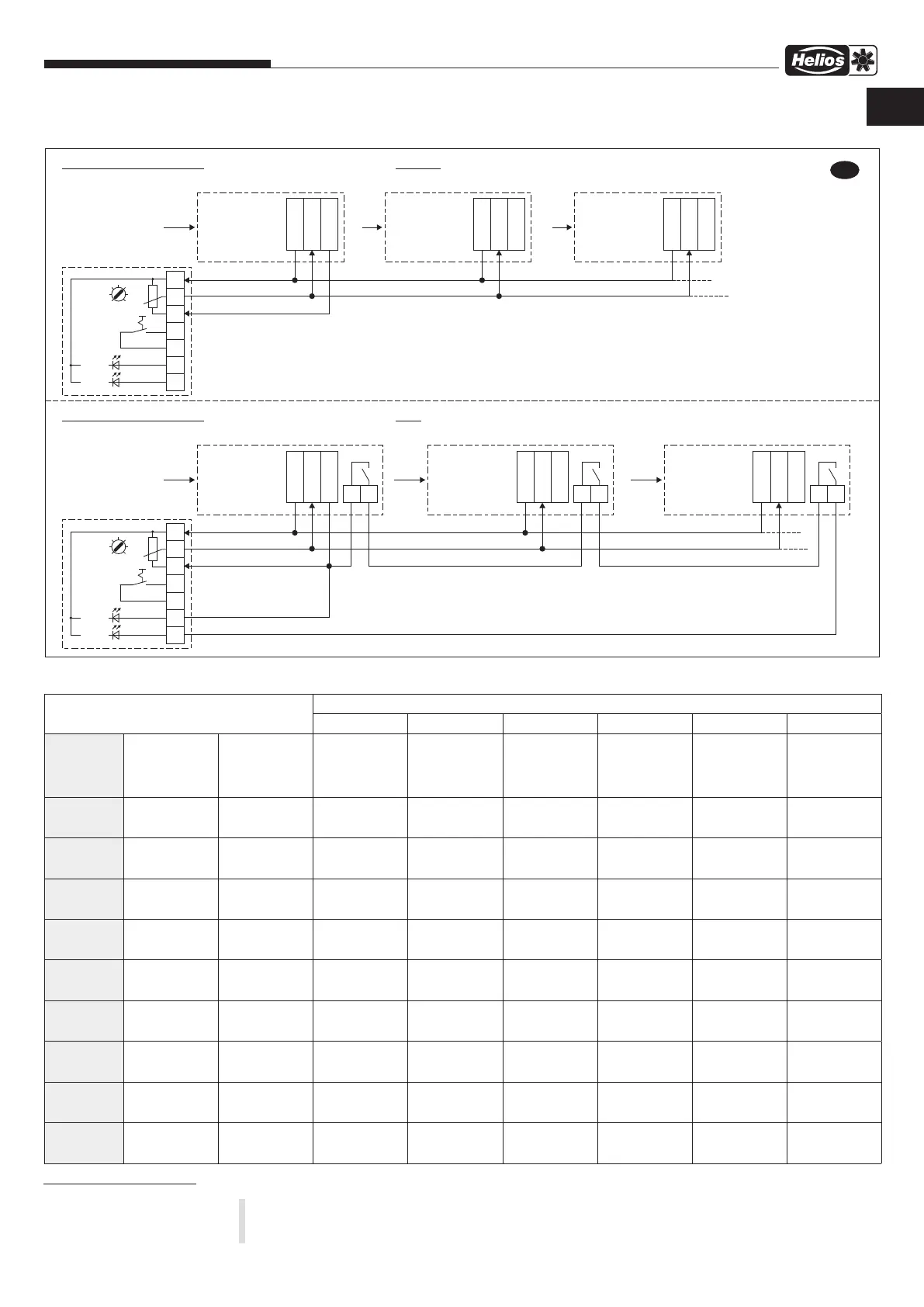
prinziple of connection: withoutPU/A 10 with multiple EC-motors LED wiring, without switch release
+10VDC
0-10V
GND
EC-fan Nr. 1
fan supply
1~ / 3~
max. 24V !
GND
output:
10 V / 10mA
0-10V input current:
0,33 mA
+10VDC
0-10V
GND
EC-fan Nr. 2
output:
10 V / 10mA
0-10V :
input current
0,33 mA
+10VDC
0-10V
GND
EC-fan Nr. 3
output:
10 V / 10mA
0-10V :
input current
0,33 mA
Attention ! Connecting in parallel of +10V DC not allowed !
Required total current in the example:
= Poti current + load current of all fans
= 1,27mA + 3 x 0,33mA = 2,26mA
PU/A Poti burden
= 7,9-16,5kOhm
at 10V
= 1,27-0,6mA
(depend on min. Poti)
Maximum possible number of fans (same types) with the sample fans
= Max. ouput current of the 1st fan - Poti current / load current of a fan
= (10mA - 1,27mA) / 0,33mA = 26,45 = max. 26 fans
PU/A 10
3
2
4
1
Potentiometer
min. rotational speed
7
6
5
LED 1
LED 2
S 1
R 1
prinziple of connection: withPU/A 10 with multiple EC-motors LED wiring via relay (closer), without switch release
+10VDC
0-10V
GND
EC-fan Nr. 1
fan supply
1~ / 3~
max. 24V !
GND
output:
10 V / 10mA
0-10V :
input current
0,33 mA
Attention ! Connecting in parallel of +10V DC not allowed !
total current needed in the example:
= Poti current + LED current + load current of all fans
= 1,27mA + 6mA + 3 x 0,33mA = 8,26mA
PU/A Poti burden
= 7,9-16,5kOhm
at 10V
= 1,27-0,6mA
(depend on min. Poti)
Maximum possible number of fans (same types) with the sample fans
= Max. output current of the 1st fan - Poti current - LED current / load current of a fan
= (10mA - 1,27mA - 6mA) / 0,33mA = 8,27 = max. 8 Ventilatoren
relay
+10VDC
0-10V
GND
EC-fan Nr. 2
output:
10 V / 10mA
0-10V :
input current
0,33 mA
relay
+10VDC
0-10V
GND
EC-fan Nr. 3
output:
10 V / 10mA
0-10V :
input current
0,33 mA
relay
LED = 6mA
85278 001 SS-1035 09.01.19
E
7.1.4 Connection principle SS-1035
7.2 Technical data for control inputs
8.0 Servicing and maintenance
m
Touching live parts will lead to electric shock.
Before any servicing and maintenance work, isolate the fan from the mains power supply and protect against
being switching on again!
Number of potential fans with
PU / A PU / A SU / A-3 10 EUR EC ETR / DER ETR / DER
Type Poti-supply
in V / mA
Control / setpoint
input in V / A (load)
from the 10 V fan
supply (no PU/A
LED)
from the10 V fan
supply (with PU/A
LED)
from the 10 V
fan supply
from the 10 V
EUR EC
supply
from the 10 V
fan supply
EDR / ETR supply
with external pow-
er supply NG24
RR EC 100 10 V / 10 mA 0-10 V / 1,0 mA
(Ri = 10 kOhm)
8 2 8 10 not possible 10
RR EC 125 10 V / 10 mA 0-10 V / 1,0 mA
(Ri = 10 kOhm)
8 2 8 10 not possible 10
RR EC 160 10 V / 10 mA 0-10 V / 1,0 mA
(Ri = 10 kOhm)
8 2 8 10 not possible 10
RR EC 200 A 10 V / 10 mA 0-10 V / 1,0 mA
(Ri = 10 kOhm)
8 2 8 10 not possible 10
RR EC 200 B 10 V / 10 mA 0-10 V / 1,0 mA
(Ri = 10 kOhm)
8 2 8 10 not possible 10
RR EC 250 A 10 V / 10 mA 0-10 V / 1,0 mA
(Ri = 10 kOhm)
8 2 8 10 not possible 10
RR EC 250 B 10 V / 10 mA 0-10 V / 1,0 mA
(Ri = 10 kOhm)
8 2 8 10 not possible 10
RR EC 315 A 10 V / 10 mA 0-10 V / 1,0 mA
(Ri = 10 kOhm)
8 2 8 10 not possible 10
RR EC 315 B 10 V / 10 mA 0-10 V / 1,0 mA
(Ri = 10 kOhm)
8 2 8 10 not possible 10
CHAPTER 8
SERVICING AND
MAINTENANCE
EN
 Loading...