17
1
Control pushbutton
The control pushbutton allows the user to switch
between the two setup memory positions. To switch
between the setups the button has to be pressed
and held for 1 second. Switching is indicated by
DVLQJOHUHGÀDVKRIWKHStatus LED. Pressing the
button for 5 seconds completely eras es the internal
PHPRU\7KLVLVLQGLFDWHGE\DFRQVWDQWÀDVKLQJRI
the Status LED.
Attention: After erasing the setups from memory
the HELIX P SIX DSP MK2 will not reproduce any
audio output.
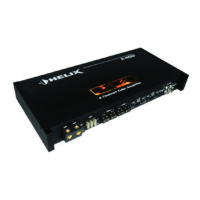
2
Status LED
The Status LED indicates the current active DSP
setup. Green means that setup 1 is load ed, orange
PHDQVWKDWVHWXSLVORDGHG$ÀDVKLQJUHGOLJKWLQ-
dicates that no setup is loaded. In that case please
load a new setup via the DSP PC-Tool software.
3
USB Input
Connect your personal computer to the
P SIX DSP MK2 using the provided USB cable. The
UHTXLUHG3&VRIWZDUHWRFRQ¿JXUHWKLVDPSOL¿HUFDQ
be downloaded from the Audiotec Fischer website
ZZZDXGLRWHF¿VFKHUFRP
Please note: It is not possible to connect any USB
storage devices.
4
Control Input
This multi-functional input is designed for HELIX
P SIX DSP MK2 accessory products like a remote
control which allows to adjust several features of
WKH VLJQDODPSOL¿HU 'HSHQGLQJ RQ WKH W\SH RI UH-
PRWHFRQWURODW¿UVWLWVIXQFWLRQDOLW\KDVWREHGH-
¿QHG LQ WKH ³'HYLFH &RQ¿JXUDWLRQ 0HQX´ RI WKH
DSP PC-Tool software.
5
Optical Input
Optical input in SPDIF format for connecting signal
sources with a digital audio output. The sampling
rate of this input must be between 12 and 96 kHz.
The input signal is automatically adjusted to the in-
ternal sample rate. In order to control the volume of
this input, we recommend to use an optional remote
control.
Notice:7KLVDPSOL¿HUFDQRQO\KDQGOHVWHUHRLQSXW
signals and no Dolby-coded digital audio stream.
6
Input Sensitivity
These potentiometers are used to adjust the input
sensitivity of the low- and highlevel inputs for the
individual stereo signals. This is not a volume con-
WURO LWV RQO\ IRU DGMXVWLQJ WKH DPSOL¿HU JDLQ 7KH
control range of the RCA / Line Input is 2 - 4 Volts
and 5 - 10 Volts for the Highlevel Input. The input
sensitivity range can be changed by repositioning
jumpers inside the device.
Attention: It is mandatory to properly adapt the in-
put sensitivity of the P SIX DSP MK2 to the signal
VRXUFHLQRUGHUWRDYRLGGDPDJHWRWKHDPSOL¿HU
7
Line Input
FKDQQHO SUHDPSOL¿HU LQSXW WR FRQQHFW VLJ-
nal sourc es such as radios. Input sensitivity is
factory-set to 4 Volts (maximum CCW position). It
is possible to vary the sensitivity between 2 and
4 Volts for each channel pair. By repositioning a
jumper inside the device the sensitivity range can
be changed to 4 - 8 Volts.
8
Highlevel Input
6-channel highlevel loudspeaker input to connect
WKH DPSOL¿HU GLUHFWO\ WR ORXGVSHDNHU RXWSXWV RI
2(0DIWHUPDUNHWUDGLRVRU2(0DPSOL¿HUVWKDWGR
QRWKDYHDQ\SUHDPSOL¿HURXWSXWV,QSXWVHQVLWLYLW\
is factory-set to 10 Volts (maximum CCW position).
It is possible to vary the sensitivity between 5 and
10 Volts for each channel pair. By repositioning a
jumper inside the device the sensitivity range can
be changed to 10 - 20 Volts.
By changing the sensitivity range the input imped-
ance of the highlevel inputs is shifted as well in or-
der to guarantee a perfect operation in combination
ZLWK2(UDGLRVDQGKLJKSRZHU2(DPSOL¿HUV,QSXW
impedance is set to 13 Ohms for a sensitivity range
Initial start-up and functions
 Loading...