Installation
Connection of HELIX P SIX DSP MK2 to the head
unit/car radio:
Caution: Carrying out the following steps will re-
quire special tools and technical knowledge. In or-
der to avoid connection mistakes and / or damage,
ask your dealer for assistance if you have any ques-
tions and follow all instructions in this manual (see
page 13). It is recommended that this unit will be
installed by an authorized HELIX dealer.
&RQQHFWLQJWKHSUHDPSOL¿HULQSXWV
Use the correct cable (RCA / cinch cable) to
FRQQHFW WKHVH LQSXWV WR WKH SUHDPSOL¿HU
lowlev el / cinch outputs of your car radio. Each
input can be assigned to any output using the
DSP PC-Tool software. The automatic turn-on
circuit does not work when using the pre-ampli-
¿HULQSXWV,QWKLVFDVHWKHUHPRWHLQSXWREM)
has to be connected to activate the HELIX
P SIX DSP MK2.
Important: It is strictly forbidden to use the
Highlevel Input DQG SUHDPSOL¿HU LQSXWV Line
Input) at the same time. This may cause severe
GDPDJHWRWKHSUHDPSOL¿HURXWSXWVRI\RXUFDU
radio.
2. Connecting the highlevel speaker inputs
The highlevel loudspeaker inputs can be con-
nected directly to the loudspeaker outputs of an
OEM or aftermarket radio using appropriate ca-
bles (loudspeaker cables with 1 mm² / AWG 18
max.). It is not mandatory to use all speaker
inputs. Make sure that the polarity is correct. If
one or more connections have reversed polarity
LWPD\DIIHFWWKHSHUIRUPDQFHRIWKHDPSOL¿HU,I
this input is used the remote input (REM) does
QRWQHHGWR EHFRQQHFWHGDVWKH DPSOL¿HUZLOO
automatically turn on once a loudspeaker signal
is received.
$GMXVWPHQWRIWKHLQSXWVHQVLWLYLW\
Attention: It is mandatory to properly adapt the
input sensitivity of the P SIX DSP MK2 to the
signal source in order to avoid damage to the
DPSOL¿HU
If you want to change the Input Sensitivity use
WKHWKUHHSRWHQWLRPHWHUVDW¿UVW7KHVHWWLQJVRI
the potentiometers affects both the lowlevel and
the highlevel inputs!
If the ex factory sensitivity range of the low-
level input (2 - 4 Volts) resp. highlevel input
9ROWVPD\QRWEHVXI¿FLHQWLWLVSRVVLEOH
to change it internally by repositioning jumpers.
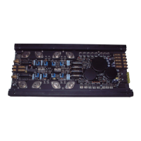
In that case you have to open the device. Re-
move the ten Phillips head screws of the bot-
tom plate to get access to the jumpers. The long
jumper (
Jumper A, 16-pins) affects the channels
A
- D and the short jumper (Jumper B, 8-pins)
the channels E and F
. Inside the device there
are two plug positions (A1 and A2) for Jumper A
and three (B1, B2 and B3) for Jumper B.
The different plug positions are explained on
page 20:
19
 Loading...