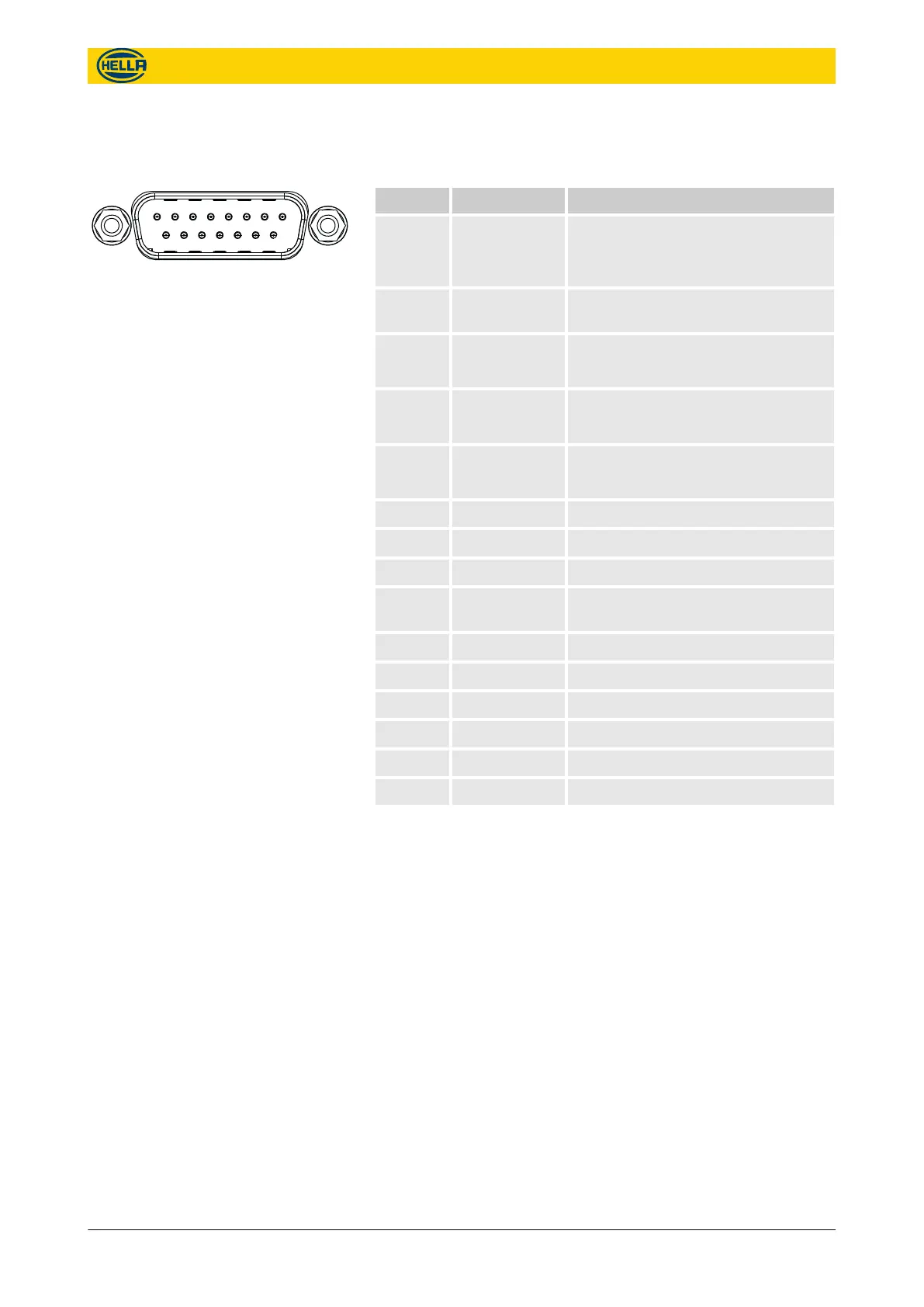
4.2.2 I/O-Port
Pin no. Name Description
1 Reset Reset Pin
(leave open, only required for correc-
tive maintenance)
2 OUT0 + Programmable output +, potential-
free
3 IN0 + Programmable input +, potential-free
(typically used for a door contact)
4 IN1 + Programmable input +, potential-free
(typically used for a door contact)
5 DID4 A Code jumper 4
(DID = "Door Identification")
6 DID3 A Code jumper 3
7 DID2 A Code jumper 2
8 DID1 A Code jumper 1
9 OUT0 - Programmable output -, potential-
free
10 IN0 - Programmable input -, potential-free
11 IN1 - Programmable input -, potential-free
12 DID4 B Code jumper 4
13 DID3 B Code jumper 3
14 DID2 B Code jumper 2
15 DID1 B Code jumper 1
Pin Allocation APS-R-PoE
1 2 3 4 5 6 7 8
9 10 11 12 13 14 15
Fig. 13: D-SUB I/O Interface
Technical data
Hardware interface specifications > I/O-Port
09.06.2017 19
The reproduction, distribution and utilization of this document as well as the communication of its contents to others
without express authorization is prohibited. Offenders will be held liable for the payment of damages.
All rights reserved in the event of the grant of patent, utility model or design.