3/28
OVERVIEW
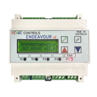
• The Hevac ENDEAVOUR is a fully programmable microprocessor based Temperature
(+ CO2) controller, with optional use of an internal 365 day Time Switch, an independent Auxiliary
Time Switch and a Run Timer all in the one model. The controller has 7 analogue inputs, 4 digital
inputs, 5 relay outputs and 2 analogue (0-10vDC) outputs. Controller I/O, time & date etc. is
displayed via a backlit LCD screen giving plain English status information together with 5 dedicated
LED’s showing the relays on/off state. The controller is primarily intended for Air Conditioning
temperature control applications where On/Off control of Heating and Cooling stages and /or
modulating P+I control of actuators / devices requiring a variable 0-10vdc control signal is required.
Typically used to control DX Air Conditioning units, Electric heating stages, modulating Heating &
Cooling Valves, VSD’s & Economy Cycle Damper sets etc. Note with this latest software version, the
Endeavour can now also be set to "Time Switch only" mode with all other none timer capabilities
disabled allowing this module to be used as a 2 channel 365 day Time Switch or Run Timer only.
• Four of the five relays are programmable for their mode of operation ie :Heat, Cool or Both (both
means the relay operates as both a heating and cooling stage), and also new to this version, relays
can now be programmed as On/Off CO2 stages or as an extra independent Auxiliary Time Switch.
The relay program menu allows individual settings of mode, deadbands, switching differentials &
time delays. The 5th relay is dedicated as a System Run (Fan / Main Time Switch) relay which can
now also be set to operate continuously whilst the controller is enabled or to cycle on & off with the
compressor (which is typical for domestic A/C systems). The two available Analogue 0-10vDC
output signals can be individually programmed for Mode of operation (heat /cool or both), start point
(deadband), range (proportional band) & method of control (P or P+I) plus also new to this version
the minimum & maximum "Y" output 0-10vdc signals can now be range limited, with any minimum
value setting automatically overridden to zero when the system is off, which is perfect for EC fan time
switch control with a minimum speed requirement.
EXTERNAL OVERRIDES & OPTIONAL CONNECTIONS
• The controller has Modbus communications capability for connecting of up to 32 controllers to our
HMI colour wall display panel for zone status, individual setpoint adjustment & system Auto/Off/On
override. Alternatively upto 247 controllers can be connected to a 3rd party BMS system for remote
control & monitoring. For added BMS monitoring, analogue input "X4" can be used to measure an
auxiliary temperature (typically the supply air temperature), "D3" is a dedicated A/C fault monitoring
input & "D4" is a general purpose on/off status input that could be used for example to monitor &
prove supply air fan running operation via a mechanical pressure switch.
• Remote System AUTO/OFF & AHR operation can be easily added by simply connecting a normally
open (N/O) switch anywhere convenient in parallel with the main temperature sensor wires X1 & M.
Momentarily shorting X1 & M results in triggering a run timer function (typically as an after hours
timer function) or / & constant shorting of X1 & M results in a system OFF function. These functions
are also duplicated on the controller terminals "D1 & M" for AUTO/OFF & AHR operation, plus
connecting a switch to "D2 & M" sets a forced manual Time switch "24/7 ON" override.
• With an optional O/A sensor connected, the Economy cycle damper operation (Y1 output) for
temperature control can be interlocked for free heating, cooling or both when the outside air
temperature conditions are favorable. The fresh air sensor (X3) is compared to the room (or return
air) temperature sensor (X1), & if the outside air temperature is measured to be more suitable for
free temperature control the motorized damper output signal (Y1) will modulate to F/A mode per
room temperature demand. The use of outside air for temperature control can also be inhibited if the
outside air temperature falls below an adjustable minimum O/A temperature (factory set at 16C for
DX or FCU coil protection ).
• With an optional CO2 sensor connected, economy cycle dampers can also be proportionally driven
to the fresh air mode to reduce high CO2 levels. The maximum damper output signal for CO2
control can be restricted in extreme O/A temperatures so as not to lose temperature control, all
settings are user adjustable. The CO2 input can now also control relays for on/off CO2 control.
• Remote Set Point devices (either passive or active) can be connected to the controller. If a passive
adjuster is connected (default setting), the controller will automatically detect and hand over set point
adjustment authority to the remote device (then ignoring the controllers UP & DOWN buttons for set
point adjustment). The remote set point potentiometer can be built into a room temperature sensor
(SRT-DSP) or as a separate stand alone device giving remote setpoint control only (SPA-D). The
range of the passive remote setpoint is fixed at 18 to 25 degrees over 0 to 10K. If an active remote
setpoint device is used the 0-10vDC is +/-5c adjustable for 0v & the top end range adjustable upto
100c. Also new : Any remote setpoint device can now be temporarily virtually disconnected by
holding the UP & DOWN buttons together for 5 seconds which hands conventional setpoint control
back to the controller to aid in commissioning & testing, but will automatically reset to remote control
after 10 minutes or can be canceled anytime by again pushing the UP & DOWN buttons together.
HEVAC Contro
l
Agencies
Pty
Ltd
www.hevac.com.au Ph
+613
95627888
28/11/19
 Loading...