HEVAC CONTROL AGENCIES PTY LTD. 7/54 HOWLEYS RD. NOTTINGHILL, VIC. 95627888 www.hevac.com.au 22/10/19
6/28
USER INTERFACE
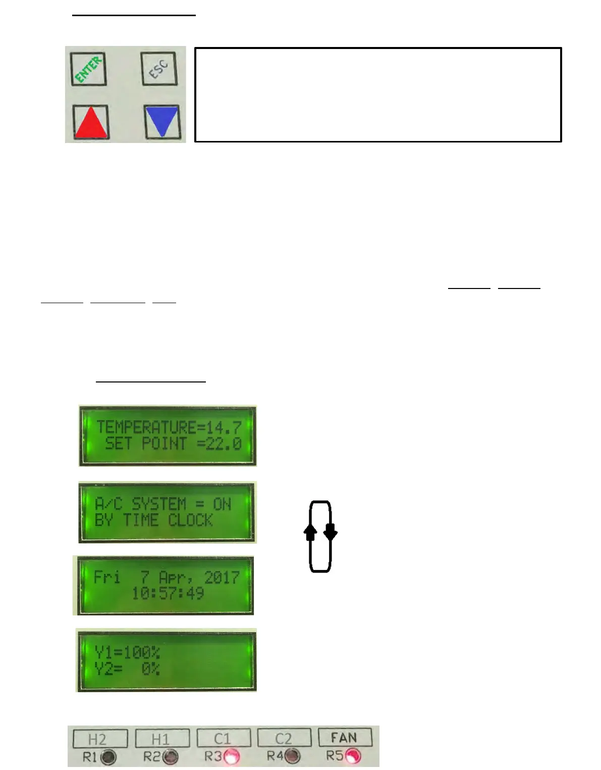
The controllers face plate has four push buttons to access & edit controller settings.
“ENTER” ACTS AS THE SAVE OR MENU OPEN BUTTON
“ESC” ACTS AS THE EXIT OR JUMP BACK TO PREVIOUS MENU BUTTON
“UP & “DOWN” BUTTONS ADJUST SETPOINT, SCROLL MENUS & TO EDIT VALUES.
The controller has a backlit (16x2) LCD screen & 5 red LED’s to give controller input & output
status. The LCD screen will automatically cycle through relevant screens displaying applicable
information as per the users programmed use of the controller ie : Room Temperature,
Setpoint, System “On By”, Time & Date, Analogue Output Values, Outside Air Temperature,
CO2 ppm levels, Supply Air temperature, analogue output levels etc.
To access the menu list as shown on page 7, press the ENTER button & use the UP & DOWN
arrow buttons to scroll through the menus, pressing ENTER to open a particular menu to edit.
The relay assignments are user programmable and as such the relay “use identifier” text box
above each LED is not factory marked and is for optional labeling by the commissioning
technician. The factory default settings for these relays, from left to right is : COMP3, COMP2,
COMP1, R/V HEAT, FAN, but could for example be assigned and marked as per the labeling
shown bottom of this page. The analogue outputs Y1 & Y2 if used, are shown as a LCD
display screen.
The keyboard can be set in three lock levels, level 0 is unlocked, level 1 allows setpoint
adjustment only, level 2 allows no adjustment. To access the lock levels press & hold all four
button for 5 seconds & release to display the existing level, adjust using the UP or DOWN
arrow buttons and press the ENTER button to set & return to the running screen.
The LCD screens will automatically cycle through each relevant display
.
* example of optional identification of
output relays by installation contractor
*
*
*
*
 Loading...