LK-LD2410C
manual
8 Radome Design Guidelines
8.1 Effect of Radome on the Performance of mmWave Sensors
• Radar waves are reflected on the radome boundary
• Loss of total power radiated or received by the radar
• The reflected wave enters the receiving channel, affecting the isolation between the transmitting and receiving channels
• Reflection may deteriorate the standing wave of the antenna, further affecting the antenna gain
• Radar waves will suffer loss when propagating in the medium. Theoretically, the higher the frequency, the greater the loss
• Electromagnetic waves are refracted to a certain extent when passing through a medium
• Affects the radiation pattern of the antenna and thus the coverage of the sensor
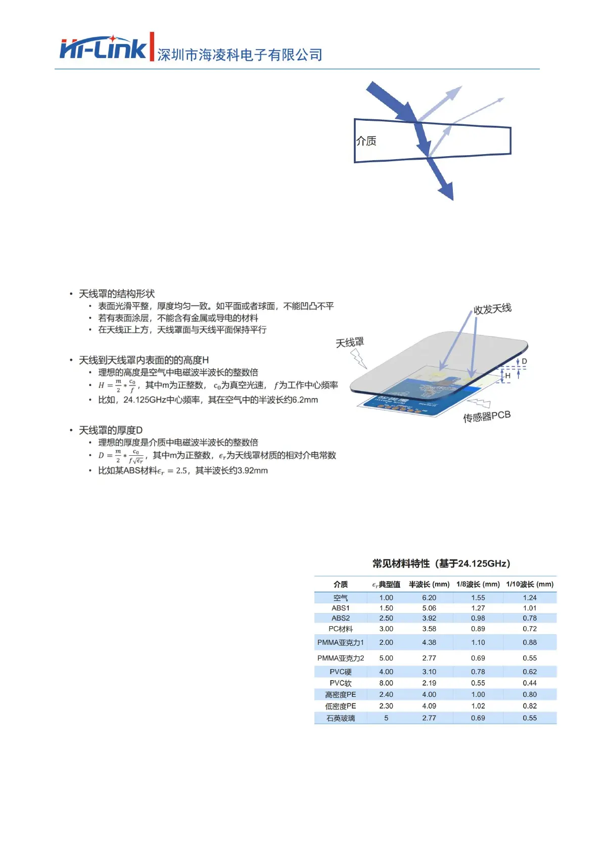
8.2 Design principles of radome
8.3common material
• Before designing, understand the material and electrical characteristics of the radome
• The table on the right is for reference only, please confirm with the supplier for the actual value
• Height H from the antenna to the inner surface of the radome
• When space permits, 1x or 1.5x wavelength is preferred
• For example, 12.4 or 18.6mm is recommended for 24.125GHz
• Error control: ±1.2mm
• Thickness D of the radome
• Recommended half-wavelength, error control ±20%
• If the half-wavelength thickness requirement cannot be met
• It is recommended to use low��s material
• Recommended thickness is 1/8 wavelength or thinner
Table 3 Common material properties of radome
• The influence of inhomogeneous materials or multi-layer composite materials on radar performance, it is recommended to make experimental adjustments during design
Page 19 of 21
 Loading...