HLK-LD2420
user manual
HLK-LD2420 supports both ceiling and wall installation methods, and the recommended method is ceiling installation.
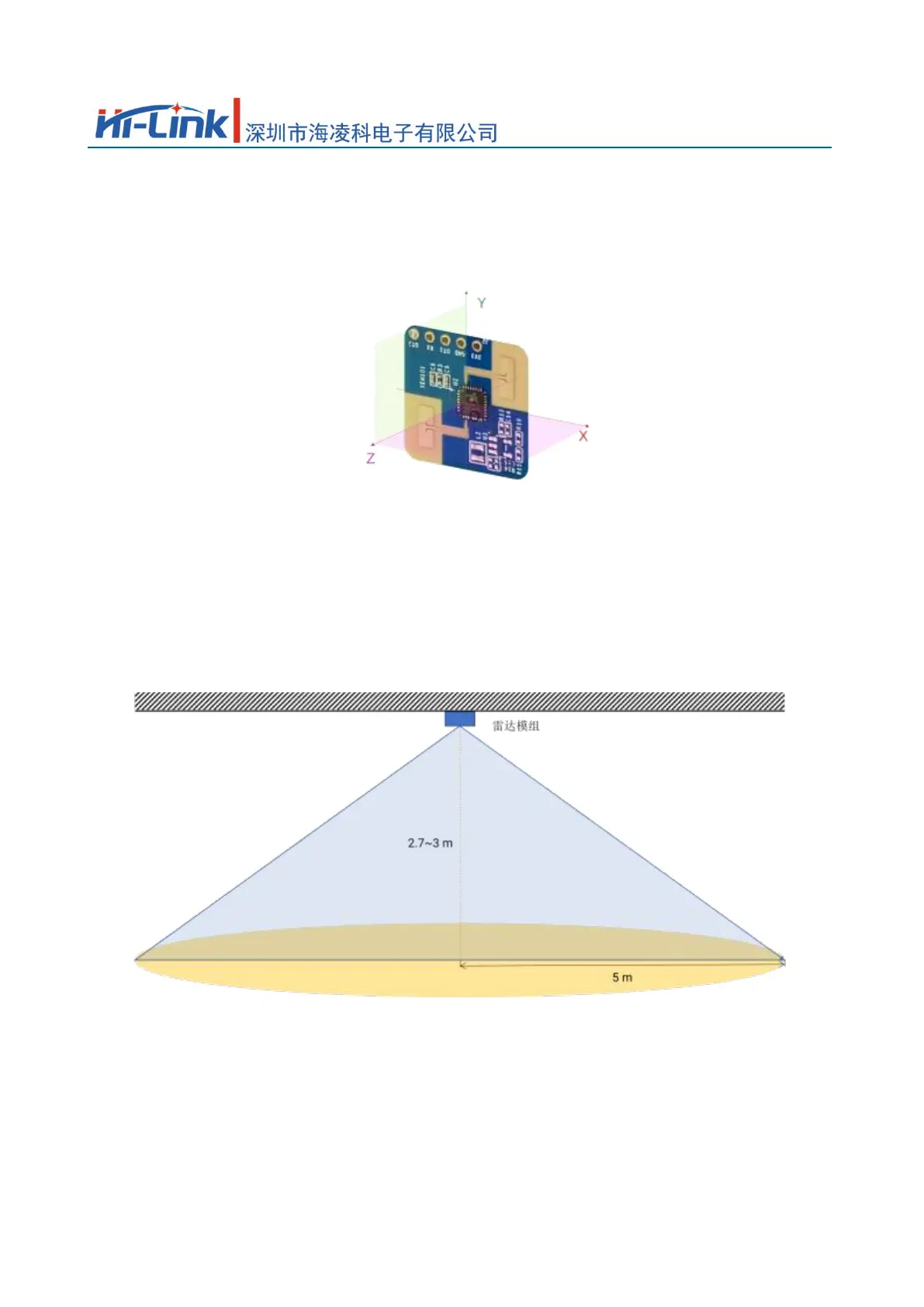
The orientation of the radar is shown in Figure 5-1. Among them, the Y-axis direction is 0°, the X-axis direction is 90°, and the Z-axis is perpendicular to the XY plane (also called
line direction).
Figure 5-1 Schematic diagram of radar module orientation
5.1.Ceiling installation
The recommended ceiling installation height is 2.7 to 3 m. The maximum motion sensing range of the ceiling-mounted HLK-LD2420 radar module in the default configuration is
A conical three-dimensional space with a bottom radius of 5m, as shown in Figure 5-2.
Figure 5-2 Schematic diagram of the detection range of the HLK-LD2420 radar module (on the ceiling)
When the ceiling installation height is 2.7m, the schematic diagram of the motion and micro-motion detection range of this reference solution is shown in Figure 5-3.
9total pages15Page
 Loading...