1. Introduction of hardware
1.1 Hardware structure
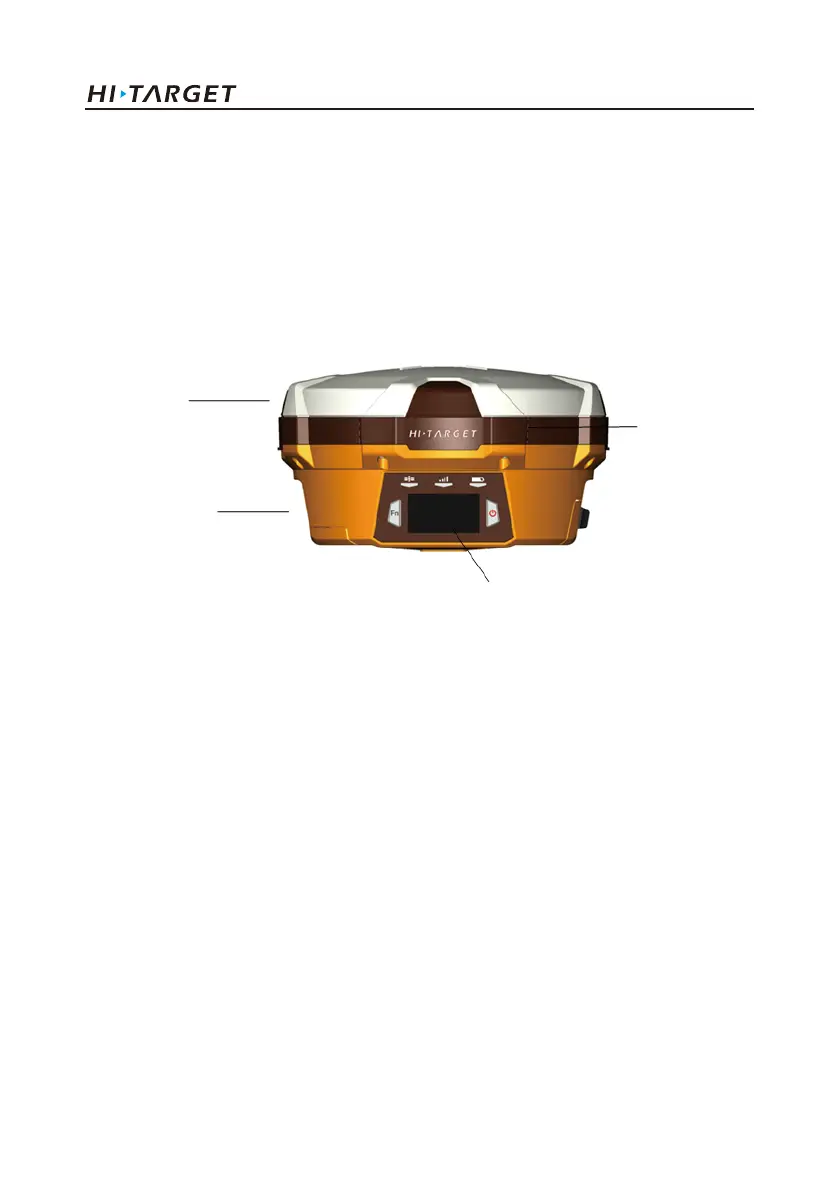
Hardware Schematic Diagram
Upper Cover
Bottom Cover
Guard Circle
Control Panel
Fig.1.1-1
Control Panel
There are FN button, Power button and three indicator lamps on the control panel .Three indicator
lamps are satellite lamp (single green lamp), status lamp (bi-color lamp of red and green) and power
lamp (bi-color lamp of red and green) from the left to the right.
FN button (Function): Set work mode, data chain, UHF transceiver channel, satellite elevation angle,
sampling interval and restoration receiver, etc.
Power button (Function): for power on and power off, Set confirmation and inquiry of the current
work mode, etc.
2
Introduction of hardware

 Loading...