140
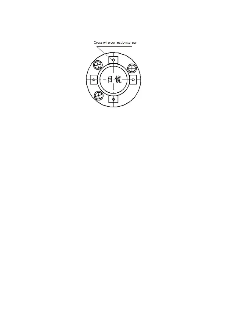
4. Screw up the correction screw and cover the reticule.
Note: Mention that users have to check the depth of
parallelism between Collimation axis Electro-optic Emission
axis
11.5 Tilt compensator
Check
1. After placing and leveling the instrument, align laser
beams and the line of connection between the instrument center
and any leveling screw on the bottom of the instrument. Then
screw up the horizontal locking screw, named X.
2. Set 0 for the vertical angle and screw up the vertical
locking screw. The instrument displays the current vertical
angle the telescope laser aims at.
3. Screw the leveling screw towards one direction for
circumferential distance around 10mm, the vertical angle
displayed will disappear through the process and „Tilt over!‟
appears to the column. It indicates that the inclination of the
 Loading...