30
FUNCTIONAL INSTRUCTIONS
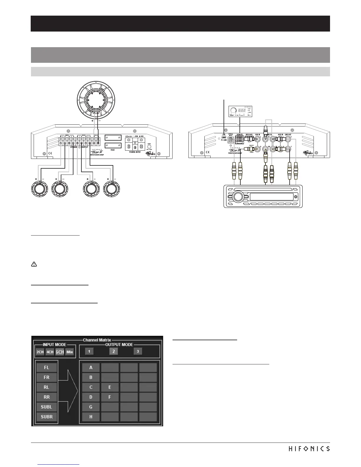
Connect the stereo RCA output (FL/FR, RL/RR and SUB OUT) of
theheadunitwithFL/FR,RL/RRandSUBINoftheamplier.
Loudspeaker
L & R, front
each 2 – 8 Ohms
Loudspeaker
L & R, rear
each 2 – 8 Ohms
Subwoofer
1 – 8 Ohms
Connect the Remote Controller
with the enclosed cable
Connect the USB port to the Compu-
ter with the enclosed USB cable
INTERCONNECTION
• Connect the RCA lineouts of the head unit with the RCA jacks LINE IN and SUB IN of the amplier with appropriate high-value
RCA cables. If your head unit is equipped with a separate subwoofer output use this for the SUB IN inputs.
• Connect the front and rear speakers with the SPEAKER OUTPUT + A - and + B - and + C - and + D - as well as the subwoofer with
+ SUB OUT - by using appropriate high-value cables.
Ensure that the total impedance load on each channel pair A/B and C/D is not lower than 2 ohms (bridged 4 Ohms) and on the sub-
woofer channel SUB OUT not lower than 1 ohm.
REMOTE CONTROLLER
Refer to page 7.
DSP-SOFTWARE SETTINGS
Now connect the DSP amplier via the included USB cable to the computer on which you installed the DSP software before.
Important: Until you have made all basic settings, turn down the volume control of the head unit all the way left to the lowest setting to
avoid damage to the sound system.
STARTING THE PROGRAM
Turn on the head unit (radio) and thus the DSP amplier. Start the DSP
software. Please also refer to the information on page 8 and 9.
CONFIGURATION OF INPUT CHANNELS
1. Chose under INPUT MODE the setting 6CH.
2. Chose under OUTPUT MODE the setting 2.
Note: If you do not operate an additional amplier on the audio output
LINE OUT E/F, no adjustments on channel pair E / F are required.
INTERCONNECTION EXAMPLE
5-channel-mode: 2 x Stereo-System (Front & Rear) + 1 x Subwoofer
 Loading...