Quick Operation Guide of Network Camera
10M/100M self-adaptive Ethernet interface
VIDEO OUT: Video output interface
AUDIO OUT: Audio output interface
POWER: Power LED indicator
MIC IN: Audio input interface
IN, G: Alarm input interface
1A, 1B: Alarm output interface
Notes:
After the powering on of the camera, pressing and holding the RESET button for about 10
seconds can reset all the parameters to the default settings.
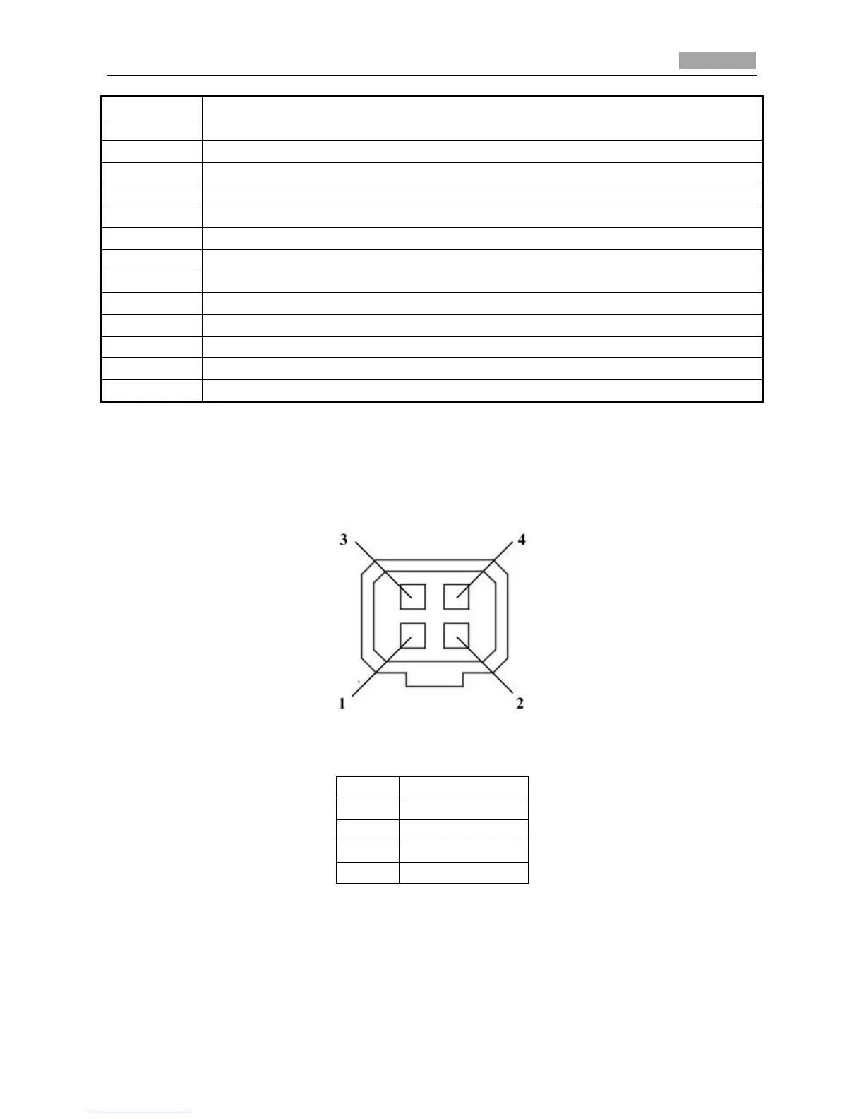
The type of auto-iris interface is shown in Figure 1-10, and the definition of each pin is shown
below:
Figure 1-10 Auto-iris Interface
Table 1-6 Pins
Damp+, Damp-, Drive+ and Drive- pins are used when the auto-iris is driven by DC.
Camera wiring Diagram: