Note:
Cable hole is required when adopting ceiling outlet to
route the cable.
3. Route the cables through the cable hole, or the side
opening.
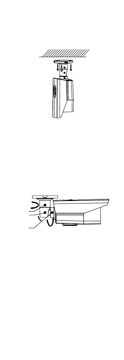
4. Attach the mounting base to the ceiling and secure
the camera with supplied screws.
Figure 2. 2 Secure the Camera to the Ceiling
Note:
The supplied screw package contains self-tapping
screws, and expansion bolts.
For cement wall, expansion bolts are required to fix
the camera. For wooden wall, self-tapping screws are
required.
5. Connect the corresponding power cord and video
cable.
6. Power on the camera to check whether the image on
the monitor is gotten from the optimum angle. If not,
adjust the camera according to the figure below to
get an optimum angle.
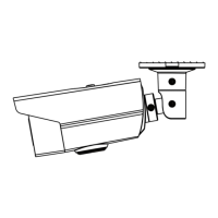
Figure 2. 3 3-Axis Adjustment
1). Loosen the No.1 adjusting screw to adjust the pan
position [0° to 360°].
2). Tighten the No.1 adjusting screw.
3). Loosen the No.2 adjusting screw to adjust the
tilting position [0° to 90°].
4). Tighten the No. 2 adjusting screw.
5). Loosen the No.3 adjusting screw to adjust the
rotation position [0° to 360°].
6). Tighten the No.3 adjusting screw.
2.3 Installation of Type II camera
Before you start:
Both wall mounting and ceiling mounting are suitable for
the turret camera. We take ceiling mounting as an
example in this section. You can take the steps of ceiling
mounting as a reference when adopting wall mounting.
Steps:
 Loading...