15
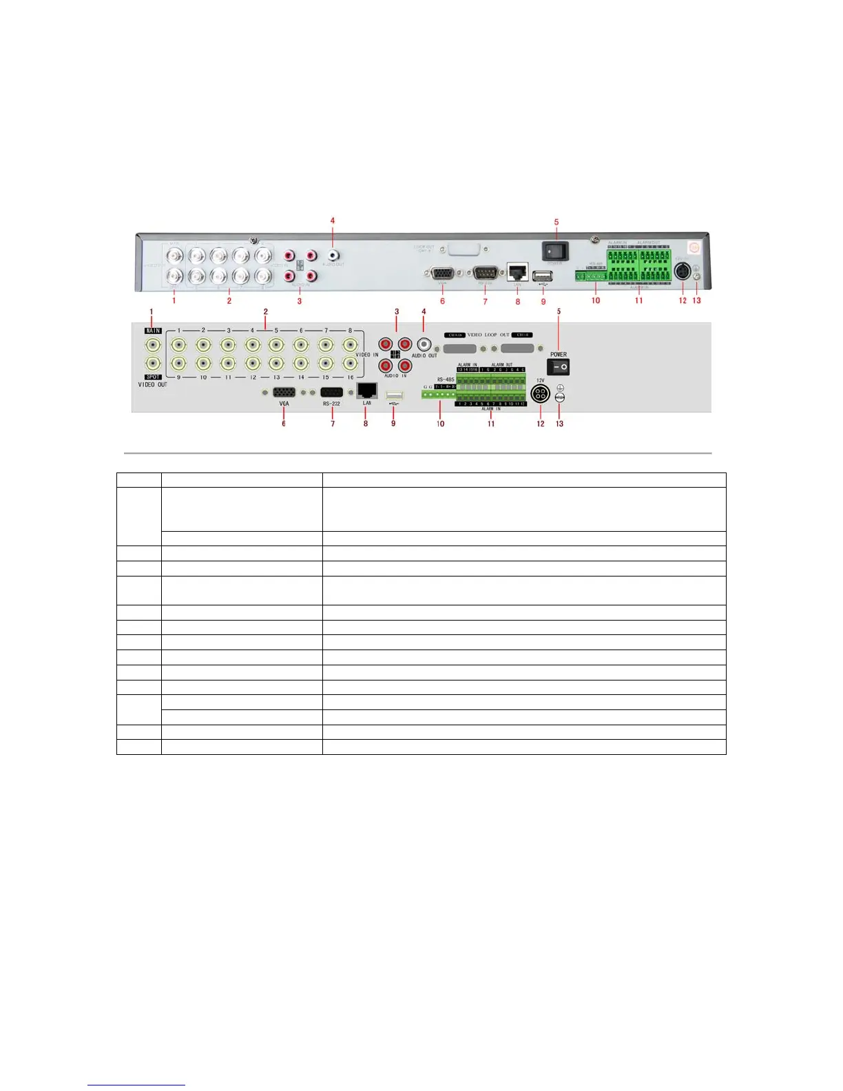
Rear Panel Diagram
Figure 8. Rear Panel Diagram
BNC connector for video output. If VGA is connected, the interface will not
function. If VGA is not connected, the interface is used as the main video
output with local video display and menu operations.
BNC connector for monitor. Single window view.
BNC connectors for analog video input.
RCA connectors for analog audio input.
RCA connector for audio output. This connector is synchronized with VIDEO
OUT.
VGA output. Display local video output and menu.
Connector for LAN (Local Area Network).
9 USB Interface Connector for USB devices.
Connector for RS-485 devices. T+, T- pin connects to PTZ.
Connector for alarm input (up to 16 channels).
Connector for alarm output (4 channels).
Ground(needs to be connected when DVR startup)
 Loading...