10
3.2 Introduction for DIP Switch
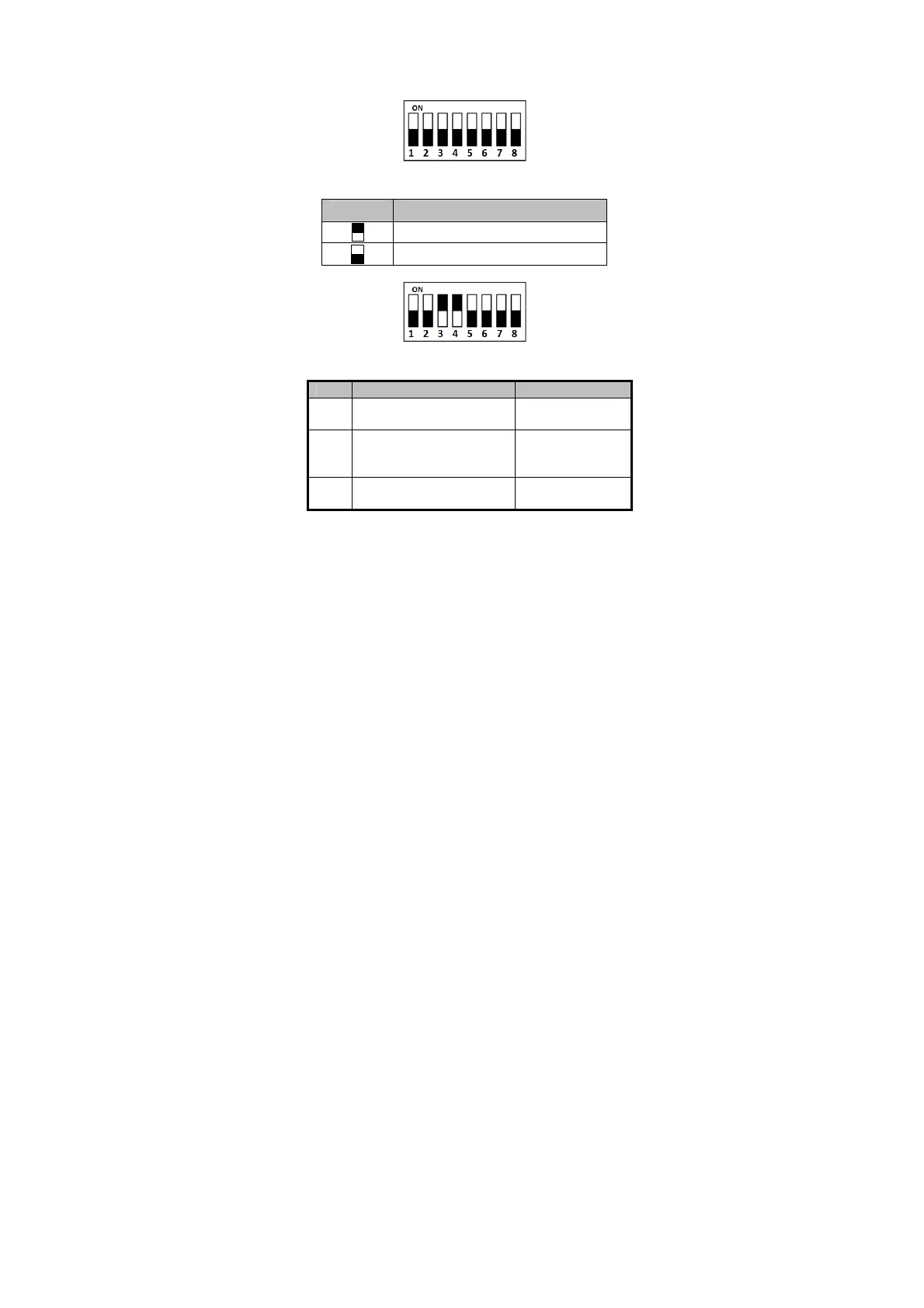
The DIP switch module is shown below. The No. of DIP switch
from left to right is 1 ~ 8.
Figure 3-2 DIP Switch Module
Table 3-1 Description of DIP Switch
Icon Description
Represent 1 in binary mode
Represent 0 in binary mode
For example, binary value of the following status is: 0000 1100.
Figure 3-3 DIP Switch Module
Table 3-2 Description of DIP Switch
1 ~ 4 Address of RS-485
1: 1
5
Read card No. or file in card.
(Only available for CPU card
1: read card No;
0: read file in card.
6
Wiegand protocol or RS-485
1: Wiegand protocol;
 Loading...