Video Door Phone·User Manual
3
3 Terminals and Wirings
3.1 Terminals and Interfaces
3.1.1 Terminals of Indoor Station
On the rear panel of the indoor station, there are 4 groups of four-wire terminals for
connecting indoor station or door station, 1 terminal for accessing the camera, and 1
terminal for power supply.
Figure 3-1 Terminals of Indoor Station
Table 3-1 Descriptions of Terminals (Indoor Station)
12 VDC Power Supply Input
Power Supply for Door Station
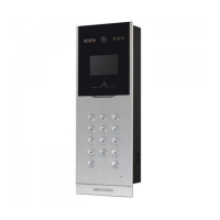
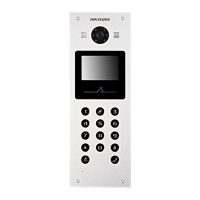
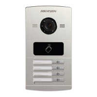
3.1.2 Terminals of Door Station
On the rear panel of the door station, there are 2 wire groups. 1 wire group is used to
connect the indoor station, and another wire group is used to connect the lock.
 Loading...
