3) Mark the gang box screw holes' posion with a marker, and
take out the gang box.
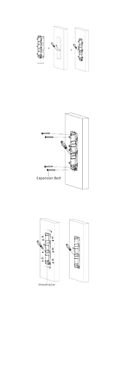
Figure 4-26 Mark the Screw Holes
4. Drill 4 holes according to marks on the wall, and insert the
expansion sleeves into the screw holes. The suggested size of
hole is 6 (diameter) × 45 (depth) mm.
5. Fix the gang box with 4 expansion bolts.
Figure 4-27 Fix the Gang Box
6. Fill the gap between the gang box and wall with concrete.
Remove the mounng ears with tool aer concrete is dry.
Figure 4-28 Remove the Mounng Ears
7. Connect cables and insert the modules.
1) Connect Cable 1 and one end of Cable 2 to the
corresponding interfaces of the main unit, then insert the
main unit into the upper grid.
24
 Loading...